
Putting-type transient temperature recorder

A transient temperature and recorder technology, applied in the field of drop-in transient temperature recorders and integrated drop-in transient temperature recorders, can solve the problems of insufficient shock resistance, slow response speed, attenuation, etc. The effect of easy measurement, small form factor, and complete temperature parameters

Inactive Publication Date: 2014-04-23
ZHONGBEI UNIV
View PDF1 Cites 0 Cited by
  • Summary
  • Abstract
  • Description
  • Claims
  • Application Information

AI Technical Summary

Problems solved by technology

[0003] 1. In special test environments such as high temperature, high pressure, and high impact, sensors are arranged at the measuring points, and the signals are uniformly connected to the acquisition system through cables. The strong electromagnetic field and strong impact in the test environment interfere with the test system. And the test system is damaged, and the complete test data cannot be recorded
[0004] 2. Thermocouples, thermistors, infrared and other temperature measurement methods have good effects on static temperature measurement, but their response speed is slow, dynamic characteristics are insufficient, and the measurement effect on transient temperature signals is not good
[0005] 3. Black body sapphire fiber optic thermometer According to the black body radiation theory, the use of sapphire fiber black body cavity sensor, tapered fiber, conduction fiber, temperature measurement photoelectric amplifier, etc. can solve the problem of high temperature measurement, but still need to rely on optical fiber to transmit temperature information, sapphire fiber The connection between the black body cavity sensor, tapered optical fiber, conductive optical fiber and temperature measurement photoelectric amplifier is complicated, it is inconvenient to use in a narrow measurement space, and it is impossible to measure the transient temperature information of a special position, and in the special measurement environment of high temperature, high pressure and high impact, the black body type The mechanical strength of the optical fiber sensor is insufficient, the impact resistance is insufficient, the tapered optical fiber and the conductive optical fiber are easily damaged, the signal coupling efficiency between the optical fibers is low, the attenuation is serious, the reliability of the measured temperature data is not high, and the integrity of the measured information cannot be guaranteed. precise

Method used


Image

  • Putting-type transient temperature recorder
  • Putting-type transient temperature recorder
  • Putting-type transient temperature recorder

Examples


Embodiment 1

[0023] Embodiment 1. Inserting type transient temperature recorder

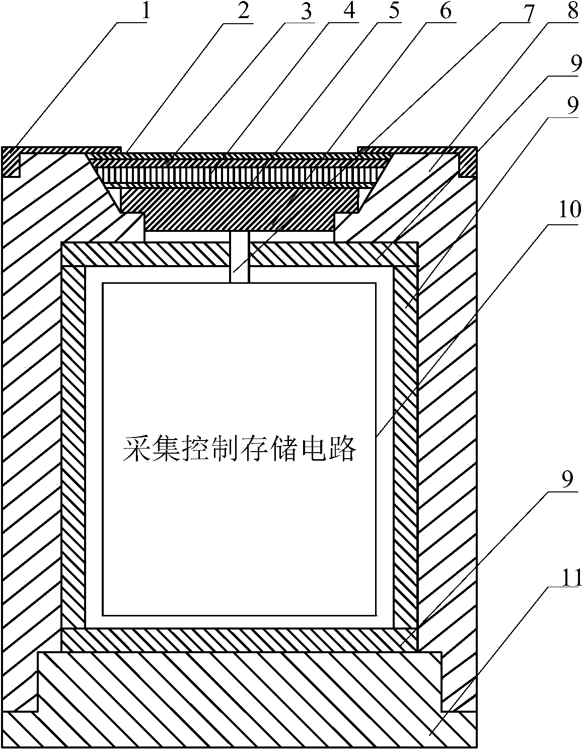
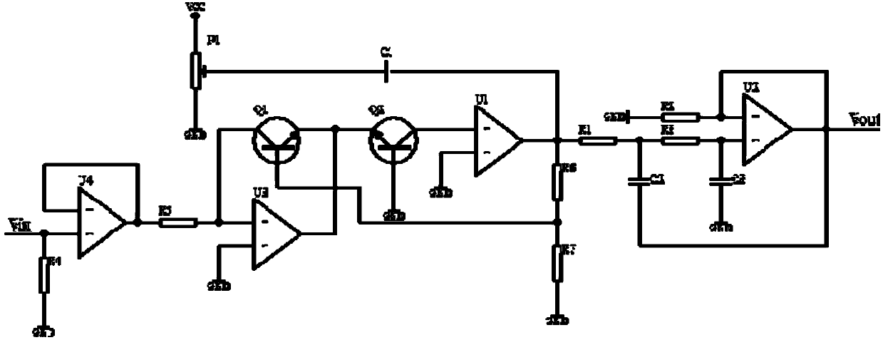
[0024] The drop-in transient temperature recorder of this example is composed of the recorder shell and the temperature sensitive unit inside the shell and the acquisition control storage circuit unit. The physical structure of the recorder in this example is given by figure 1 show, figure 1 It is a schematic diagram of the structure of the embedded temperature transient recorder. figure 1 Middle: 1 is the protective cover, 2 is the ceramic layer, the thickness is 1.0-20.0μm, 3 is the metal film, the thickness is 1.0-50.0μm, 4 is the sapphire substrate, the thickness is 1.0-10.0mm, 5 is the narrow-band filter film, The thickness is 10.0-100.0nm, 6 is a photoelectric converter, 7 is a wire, 8 is a mechanical casing, 9 is a buffer rubber pad, 10 is an acquisition control storage circuit, and 11 is a casing cover. figure 2 Shown is the block diagram of the temperature sensitive unit structure, figure 2 Mi...

Embodiment 2

[0025] Embodiment 2. Inserting type transient temperature recorder

[0026] The specific structure of the drop-in transient temperature recorder in this example can be Figure 1 ~ Figure 4 etc. jointly show that the difference between the embedded transient temperature recorder of this example and the embedded transient temperature recorder of Embodiment 1 is: this example deposits a metal film 3 on the front surface of the sapphire substrate, and the metal film It can be made of metal iridium or platinum; a ceramic layer 2 with high thermal conductivity is deposited on the metal film, and the ceramic layer can be made of boron carbide B 4 C, or silicon nitride Si 3 N 4 Manufacture; a narrow-band filter film 5 is plated on the rear surface of the sapphire substrate by a pulsed laser deposition process, and the narrow-band filter film can be made of silicon dioxide SiO 2 manufacture. All the rest of the embedded transient temperature recorder of this example are the same as...


PUM

PropertyMeasurementUnit
Thicknessaaaaaaaaaa

Abstract

The invention discloses a putting-type transient temperature recorder, and pertains to the technical field of transient high temperature tests. The recorder is composed of a metal shell, a temperature sensitive unit arranged in a window formed in the end surface, and an acquisition, control and storage circuit unit arranged in the shell. The temperature sensitive unit takes black-body radiation sapphire as the base, the front surface of the base is provided with a metal thin film, a ceramic layer is arranged on the metal thin film, the rear surface of the base is provided with a narrowband filter membrane, and the rear surface of the narrowband filter membrane is provided with a photoelectric transformer. The acquisition, control and storage circuit unit is formed by miniaturizing and integrating temperature signal conditioning, acquisition and conversion, control and storage, clock, trigger, interface circuits and the like into an acquisition, control and storage circuit module, and the module is cured integrally through epoxy resin. The recorder has the following advantages that the recorder is a contact-type integrated instrument, advantages of no lead, small size, fast response, high accuracy and severe environment resistance can be realized, transient temperature signals are acquired on a real-time basis, triggering, storing and recording are performed automatically according to the signals, and the transient temperature recorder is worth using and popularizing.

Description

technical field [0001] The drop-in transient temperature recorder disclosed by the invention belongs to the technical field of transient high temperature testing, and specifically relates to an integrated drop-in transient temperature recorder based on the principle of blackbody temperature measurement. Background technique [0002] The main disadvantages of the existing transient temperature test system are: [0003] 1. In special test environments such as high temperature, high pressure, and high impact, sensors are arranged at the measuring points, and the signals are uniformly connected to the acquisition system through cables. The strong electromagnetic field and strong impact in the test environment interfere with the test system. And the test system is damaged, and the complete test data cannot be recorded. [0004] 2. Thermocouples, thermistors, infrared and other temperature measurement methods have good effects on static temperature measurement, but their respons...

Claims


Application Information

Patent Timeline
IPC IPC(8): G01J5/52
Inventor 尤文斌丁永红马铁华石正全祖静张瑜
Owner ZHONGBEI UNIV
Learn More