Geothermal energy compound type gas-fired cooling, heating and power trigeneration system

A combined heat, power and cooling technology, used in geothermal power generation, hot water central heating systems, heating systems, etc., can solve the problem of insufficient heat recovery of flue gas, no recovery of condensed heat of flue gas, and difficulty in reaching the system. Energy utilization efficiency and other issues, to achieve the effect of improving energy utilization efficiency, reducing emissions, and alleviating difficulties in grid connection

Active Publication Date: 2014-04-30
TSINGHUA UNIV +1
View PDF7 Cites 11 Cited by
  • Summary
  • Abstract
  • Description
  • Claims
  • Application Information

AI Technical Summary

Problems solved by technology

However, the current technology does not fully recover the flue gas heat, and there is still a large amount of flue gas con...

Method used


Image

  • Geothermal energy compound type gas-fired cooling, heating and power trigeneration system
  • Geothermal energy compound type gas-fired cooling, heating and power trigeneration system
  • Geothermal energy compound type gas-fired cooling, heating and power trigeneration system

Examples


Embodiment 1

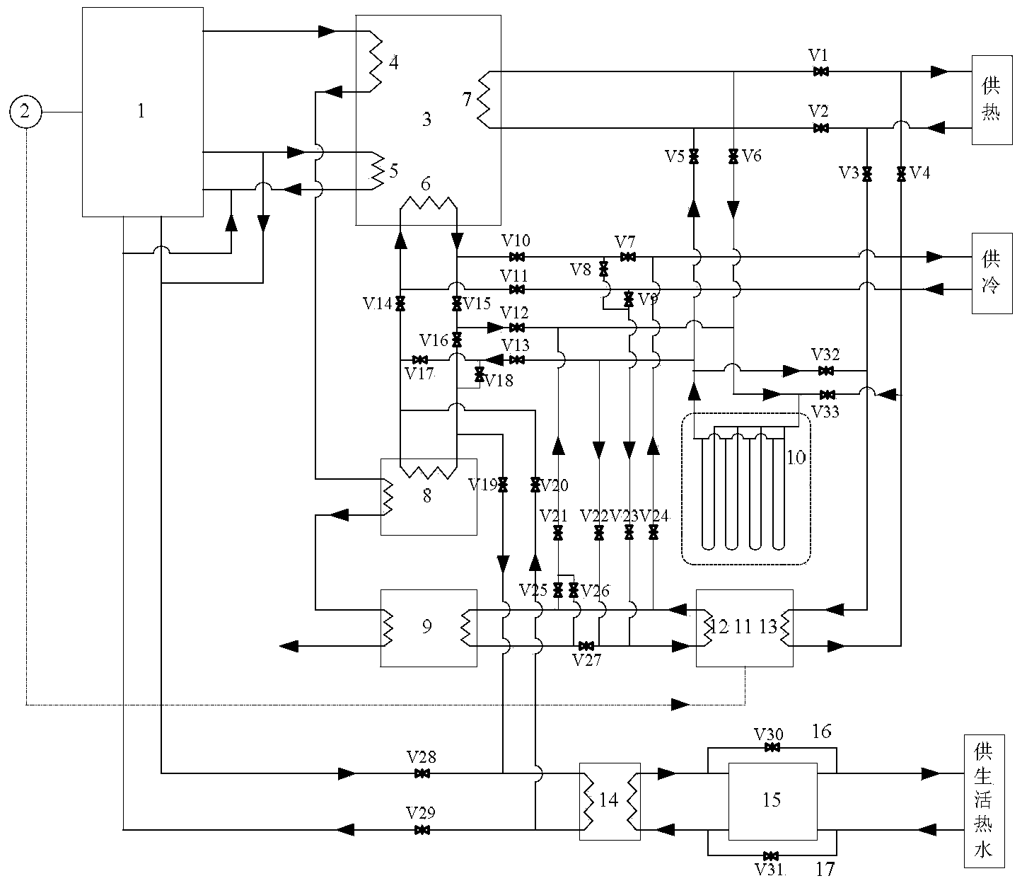
[0022] Such as figure 2 As shown, under heating condition 1, the jacket water channel outlet of the gas internal combustion engine 1 is connected to the water channel inlet of the second generator 5; the water channel outlet of the second generator 5 is connected to the cylinder jacket water channel inlet of the gas internal combustion engine 1 connected; the water outlet of the evaporator 6 of the absorption heat pump 3 is respectively connected with the water inlet of the first spray flue gas heat exchanger 8 and the water inlet of the buried pipe heat exchanger 10; the first spray flue gas The waterway outlet of the gas heat exchanger 8 is connected to the waterway inlet of the evaporator 6 of the absorption heat pump 3; The waterway inlet of the evaporator 12 of the electric heat pump 11 is connected to the waterway inlet of the evaporator 12 respectively; The waterway outlet of the second spray type flue gas heat exchanger 9 is connected with the waterway inlet of the e...

Embodiment 2

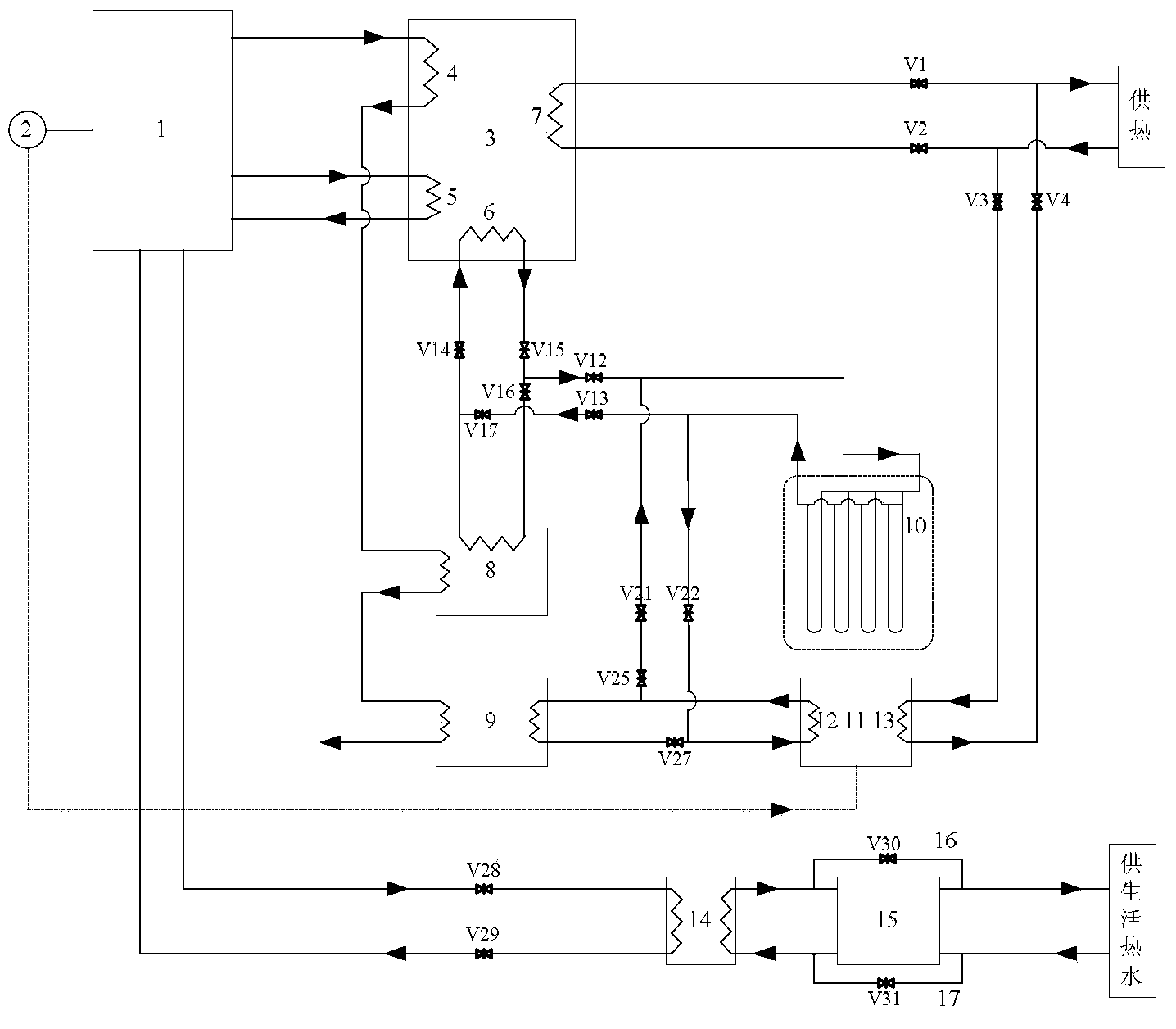
[0025] Such as image 3 As shown, the heating condition 2 is based on the heating condition 1, adding a pipeline from the waterway outlet of the buried pipe heat exchanger 10 to the waterway inlet of the first spray flue gas heat exchanger 8 As well as the eighteenth valve V18 of the valve on the pipeline, a pipeline from the water outlet of the second spray type flue gas heat exchanger 9 to the water inlet of the buried pipe heat exchanger 10 is added and the pipeline located on the pipeline The valve of the twenty-sixth valve is V26. The water outlet from the evaporator 6 of the absorption heat pump 3 passes through the buried tube heat exchanger 10 and the first spray flue gas heat exchanger in turn to heat up and returns to the evaporator 6 to release heat. The water output from the evaporator 12 of the electric heat pump 11 passes through the second spray type flue gas heat exchanger 9 and the buried pipe heat exchanger 10 in turn to heat up and then returns to the evapo...

Embodiment 3

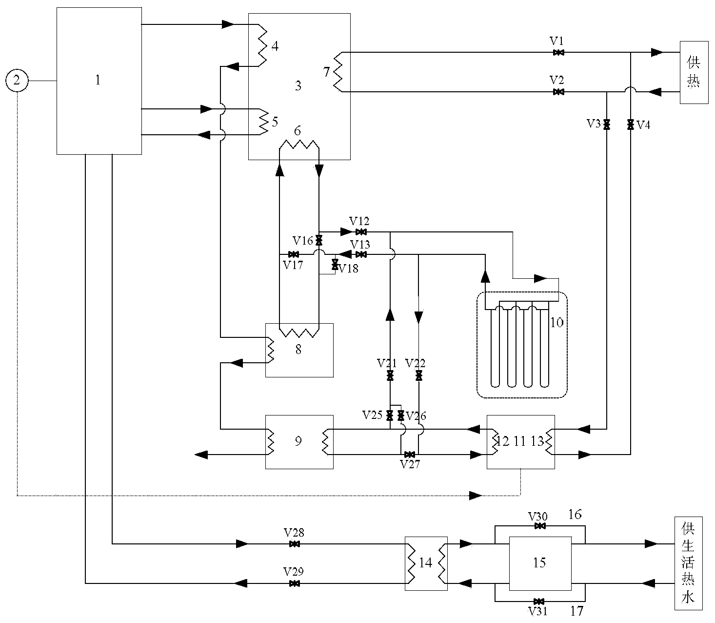
[0027] Such as Figure 4 As shown, on the basis of heating condition 1, the heating condition 3 reduces the intercooling water pipeline between the gas internal combustion engine 1 and the water-water heat exchanger 14, and the high-temperature cylinder liner moisture from the gas internal combustion engine 1 is two All the way into the second generator 5 of the absorption heat pump 3 to release heat and return to the gas internal combustion engine 1, and all the way to the water-water heat exchanger 14 to release heat and return to the gas internal combustion engine 1. The opening and closing of the valve under this heating condition is the same as that of Embodiment 1.


PUM


Abstract

The invention relates to a geothermal energy compound type gas-fired cooling, heating and power trigeneration system realizing thorough recovery of flue gas condensation heat. The system comprises a gas engine, a power generator, an absorption heat pump, an electric heat pump, a first spraying type gas-gas heater, a second spraying type gas-gas heater, a ground heat exchanger, a water-water heat exchanger, a heat storage water tank, connection pipes and valves. Heating and cooling can be realized by the system, the system is capable of thoroughly recovering flue gas condensation heat to greatly lower exhaust gas temperature and reduce pollutant emission and further capable of extracting superficial terrestrial heat to realize complementation of fossil energy and renewable energy sources, and improvement of energy utilization efficiency of the system is facilitated.

Description

technical field [0001] The invention relates to a gas-fired combined heat-electricity-cooling system, in particular to a geothermal energy composite gas-fired combined heat-power-cooling system for deeply recovering the condensation heat of flue gas. Background technique [0002] Due to its high efficiency, environmental protection and other advantages, the gas-fired cogeneration system has been valued and developed rapidly at home and abroad. In order to further improve the energy utilization efficiency of the gas-fired combined heat, power, and cooling system, certain technical means are usually used to tap the heat of the exhaust smoke of the engine for heating and cooling. However, the current technology does not fully recover the flue gas heat, and there is still a large amount of flue gas condensation heat that has not been recovered, making it difficult to further improve the energy utilization efficiency of the system. Therefore, it is urgent to develop a gas-fired ...

Claims


Application Information

Patent Timeline
IPC IPC(8): F25B29/00F25B27/02F25B15/00F24D3/18F24J3/08
CPCY02A30/274Y02B10/40Y02B30/12Y02B30/625Y02E10/10
Inventor 王潇付林赵玺灵李庆生皮显松
Owner TSINGHUA UNIV
Why Eureka
Try Eureka