
Manufacturing method of spherical milling cutter with micro-cutting milling blade array structure

A technology of spherical milling cutter and array structure, which is applied to milling cutters, milling machine equipment, metal processing equipment, etc., can solve the problems of time-consuming and labor-intensive processing, and achieve the effect of avoiding secondary clamping and tool replacement and reducing errors

Active Publication Date: 2014-05-07
SOUTH CHINA UNIV OF TECH
View PDF5 Cites 10 Cited by
  • Summary
  • Abstract
  • Description
  • Claims
  • Application Information

AI Technical Summary

Problems solved by technology

[0003] The purpose of the present invention is to overcome the shortcomings of the existing technology that it is difficult to directly process micro-groove structures on the surface of parts, and the processing is time-consuming and labor-intensive, and to provide a kind of workpiece that can be formed on aluminum alloy, titanium alloy, copper, mold steel and other workpieces at one time. Method for manufacturing spherical milling cutter with micro-cutting edge array structure with micro-groove structure surface directly milled

Method used


Image

  • Manufacturing method of spherical milling cutter with micro-cutting milling blade array structure
  • Manufacturing method of spherical milling cutter with micro-cutting milling blade array structure
  • Manufacturing method of spherical milling cutter with micro-cutting milling blade array structure

Examples


Embodiment 1

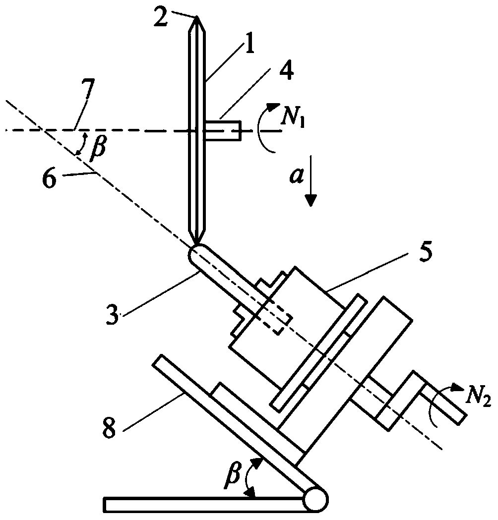
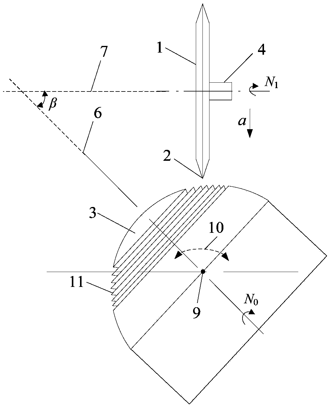
[0028] Such as figure 1 As shown, a diamond grinding wheel 1 (diameter 160 mm, thickness 4 mm) was finely trimmed into a V-shaped tip 2 and installed on the grinding wheel shaft 4 of a CNC precision grinding machine (SMART‐B818). Then place the indexer 8 (MCL-C3×4) on the horizontal workbench, then place the fixture (Michelin three-jaw grinder MCL-550) 5 on the indexer 8, and place the double-edged spherical milling cutter 3 (ball head radius 6mm , the diameter of the milling cutter is 12mm, and the length of the milling cutter is 75mm) is clamped on the fixture 5, so that the angle β between the axis 6 of the spherical milling cutter and the axis 7 of the grinding wheel is 45 degrees. The V-tip diamond grinding wheel has a particle size of 600 mesh and is composed of diamond abrasive and bronze bond. The included angle of the V-tip of the grinding wheel is 60 degrees. The material of the spherical milling cutter is tungsten carbide with a hardness of 70-80HRC.

[0029] Such...

Embodiment 2

[0032] The processing mode of this embodiment is the same as that of Embodiment 1. The difference is that when using a spherical milling cutter with a micro-cutting edge structure array to mill the micro-groove structure surface of G-STAR die steel (HRC40-50), the milling cutter speed is 3000 rpm and the feed rate is 100 mm / min with a feed depth of 10 microns. The processed micro-groove structure has a depth of 90 microns, a groove angle of 63.5 degrees, a tip radius of 15 microns at the bottom of the groove, and a micro-groove spacing of 600 mm. The surface of the micro-grooves is smooth without burrs.

Embodiment 3

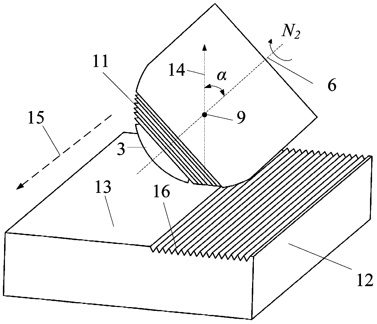
[0034] Such as Figure 4 As shown, if the surface of the workpiece 12 is designed with a curved surface 13, the aluminum alloy workpiece is first processed into a curved surface with a spherical milling cutter without a micro-cutting edge structure array. The measurement is 0.5mm, the tool radius is 6mm, the rotational speed is 5000rpm, and the feed rate is 1000mm / min. Then, a spherical milling cutter with a micro-cutting edge structure array is used to produce a micro-groove array on the processed curved surface. The grooving processing parameters are 0.1 mm back cut, 5000 rpm rotation speed, and 800 mm / min feed speed. Specifically, in the milling process, the normal direction 14 of the tangent point between the spherical surface of the milling cutter and any curved surface of the workpiece is always maintained at a fixed angle α=45°, and the spherical milling cutter is processed along the curved surface where the normal radius of the tangent point is r The knife track 15 of...


PUM

PropertyMeasurementUnit
Angleaaaaaaaaaa
Diameteraaaaaaaaaa
Heightaaaaaaaaaa

Abstract

The invention discloses a manufacturing method of a spherical milling cutter with a micro-cutting milling blade array structure. The method comprises the following steps of moving a center point of the spherical milling cutter to the part just under a V-shaped tip end of a diamond grinding wheel, enabling the diamond grinding wheel to do reciprocating movement in the horizontal cutting direction and continuously feed downwards, continuously cutting the rotary spherical surface of the milling cutter, cutting into a V shape, processing a round circle-shaped micro groove on the spherical surface of the milling cutter through the rotating of the spherical milling cutter, processing the other V-shaped groove on the adjacent position, and forming the micro-cutting milling blade on the crossing part of the two adjacent V-shaped grooves; gradually shaping the micro-cutting milling blade into a sharp angle by the V-shaped tip end of the diamond grinding wheel and micro diamond grinding particles at the two side surfaces of the diamond grinding wheel. When the spherical milling cutter with the micro-cutting milling blade array structure is used, the microgroove structure surface can be directly milled and processed on the surfaces of workpieces made of the following materials, such as aluminum alloy, titanium alloy, copper and die steel in one-time forming way, the processing efficiency is greatly improved, the processing cost is reduced, and the problems of secondary clamping, cutter replacement and the like are avoided.

Description

technical field [0001] The invention relates to a milling cutter, in particular to a method for manufacturing a spherical milling cutter with a micro-cutting edge array structure, and the milling cutter is used for microstructure surface forming processing of parts such as titanium alloy, die steel, and hard alloy; The invention belongs to the technical field of precision manufacturing of superhard tools. Background technique [0002] Microstructure arrays less than 1 mm can be processed on the surface of automobile transmission parts, extrusion hard cores, aviation flying objects, mechanical tools, etc., which can add new surface functions, such as improving power transmission efficiency and enhancing the extrusion of soft steel. Compression efficiency, reduce flight resistance, prolong tool life, etc. At present, the microstructure manufacturing technology mainly relies on processing methods such as laser etching, electrochemical corrosion, and ion beam. However, these pr...

Claims


Application Information

Patent Timeline
IPC IPC(8): B24B3/02
CPCB24B3/08
Inventor 谢晋黎宇弘程剑吴可可杨林丰罗敏健
Owner SOUTH CHINA UNIV OF TECH
Learn More