Method and apparatus for manufacturing optical fiber perform extramural cladding

A technology of optical fiber preform and outer cladding, which is applied in the field of optical communication, can solve the problems of outer diameter fluctuation and large fluctuation of optical fiber preform outer diameter, and achieve the effects of small outer diameter fluctuation, good cooling effect and high deposition efficiency

Inactive Publication Date: 2014-05-07
ZHEJIANG FUTONG OPTICAL FIBER TECH
View PDF6 Cites 16 Cited by
  • Summary
  • Abstract
  • Description
  • Claims
  • Application Information

AI Technical Summary

Problems solved by technology

[0006] In view of this, the present invention provides a method for manufacturing the outer cladding of an optical fiber preform, which solves the problem of large fluctuations in the outer diameter of the optical fib...

Method used


Image

  • Method and apparatus for manufacturing optical fiber perform extramural cladding
  • Method and apparatus for manufacturing optical fiber perform extramural cladding
  • Method and apparatus for manufacturing optical fiber perform extramural cladding

Examples


example 1

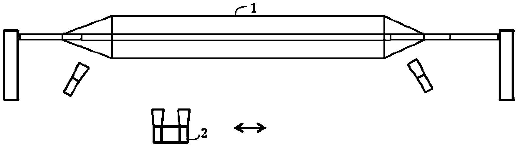
[0079] Example 1: Production under dual-lamp deposition conditions

[0080] Use H 2 , O 2 As combustion gas, SiCl 4 as SiO 2 Raw materials generated by dust are fed in at a certain flow rate figure 1 For the deposition lamp shown, the distance between the lamps is 200mm, the traverse distance is 1200mm, the initial layer traverse speed is 100mm / min, and the traverse speed is gradually increased to 900mm / min, and remains unchanged. The characteristics of the preform are as follows:

[0081] Dust preform density: 0.52g / cm3.

[0082] Deposition rate: 30g / min.

[0083] Bubble defects: None.

[0084] Maximum corrugation on the surface of glass preform (between adjacent 40mm): 0.1mm.

[0085] The characteristics of the optical fiber preform described in Example 1 all meet the requirements of relevant standards.

example 2

[0086] Example 2: Multi-lamp deposition production with lateral offset

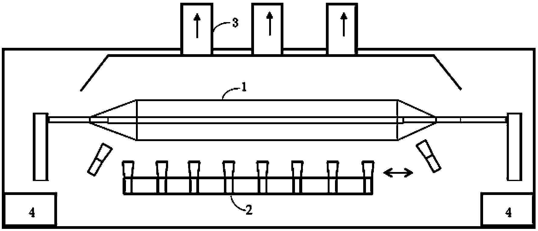
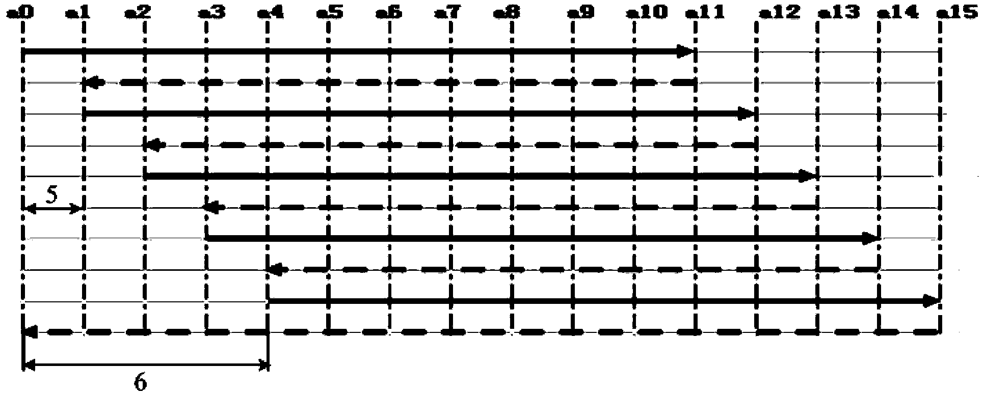
[0087] Use H 2 , O 2 As combustion gas, SiCl 4 as SiO 2 Raw materials generated by dust are fed in at a certain flow rate figure 2 For the deposition lamp array shown, the lamp distance is 200mm, according to V=2RL 0 / (2N+1), the traversing speed is 960mm / min, the initial layer traversing speed is 100mm / min, gradually increase to the traversing speed 960mm / min, the traversing distance is 200mm, and the same distance is offset each time, and the test is 3 times , 2 of which cracked at 15Kg, and the result of 1 uncracked is as follows:

[0088] Dust preform density: 0.55g / cm3.

[0089] Deposition rate: 80g / min.

[0090] Bubble defects: None.

[0091] The maximum corrugation on the surface of the glass preform (between adjacent 40mm): 0.2mm.

[0092] The characteristics of the optical fiber preform described in Example 2 meet the requirements of relevant standards. The deposition rate of a single r...

example 3

[0093] Example 3: Multi-lamp deposition production with lateral movement and gas flow control

[0094] Use H 2 , O 2 As combustion gas, SiCl 4 as SiO 2 Raw materials generated by dust are fed in at a certain flow rate figure 2 For the deposition lamp array shown, the lamp distance is 200mm, according to V=2RL 0 / (2N+1), the traversing speed is 960mm / min, the initial layer traversing speed is 100mm / min, and gradually increases to the traversing speed 960mm / min, the traversing distance is 200mm, and each time the offset is the same distance, with the traversing The speed changes, and the combustion gas flow is adjusted accordingly, that is, the gas flow increases synchronously when the speed increases. The test is performed 3 times, and the tests are all successfully completed. The characteristics of the optical fiber preform produced are as follows:

[0095] Optical fiber preform density: 0.60g / cm3.

[0096] Bubble defects: None.

[0097] Maximum corrugation on the surf...


PUM

PropertyMeasurementUnit
Densityaaaaaaaaaa
Densityaaaaaaaaaa
Densityaaaaaaaaaa

Abstract

The invention discloses a method for manufacturing an optical fiber perform extramural cladding, and the prior deposition method usually employs a double-lamp deposition, which has the disadvantages of long deposition time, reduced production efficiency and high cost. According to the invention, an external gas-phase deposition method is used for producing optical fiber perform, and multi-lamp deposition is employed; the quantity of the lamp is more than three times of that in the routine process, and lamps are horizontally and upwardly arranged in a straight line with a certain internal; center of lamp flames aligns to a cylindrical initial starting rod at a certain rotating speed, and carries out a reciprocating motion according to a certain rule relative to the initial starting rod, and thereby silica dust adheres to the surface of the initial starting rod. The invention employs a transverse deposition, controls of lamp moving mode, gas flow, deposition weight, reciprocating times, exhaust air quantity and two-end heat assisting lamp gas flow, which can effectively reduce fluctuation of external diameter of optical fiber perform, and the invention has the advantages of good reproducibility of external diameters between optical fiber performs, high production efficiency, low cost and high deposition speed which is increased by more than three times.

Description

technical field [0001] The invention belongs to the technical field of optical communication, is applied to the manufacture of optical fiber preform rods, and particularly relates to a method and device for manufacturing the outer cladding of optical fiber preform rods. Background technique [0002] The current method of producing optical fiber preform by external vapor deposition process mainly adopts such as figure 1 In the deposition form shown, in this method, the raw material gas, combustible gas and inert gas are passed into the deposition lamp 2, and hydrolysis and oxidation reactions occur in the flame ejected from the deposition lamp (hereinafter referred to as the lamp) to generate glass dust particles. Under the effect of thermophoresis, it adheres to the surface of the initial starting rod, deposits to form a glass particle dust rod 1, and finally obtains the required optical fiber preform rod through further processing. However, due to the limitation of process...

Claims


Application Information

Patent Timeline
IPC IPC(8): C03B37/018
CPCY02P40/57
Inventor 卢卫民刘连勇吴海港朱晓波杨军勇章海峰方子乾丁熊
Owner ZHEJIANG FUTONG OPTICAL FIBER TECH
Why Eureka
Try Eureka