Vehicle-mounted high-speed road inspection system and data acquisition and processing method

A technology of expressway and inspection system, applied in the direction of inspection time patrol, etc., can solve the problems of high rate of missed judgment, misjudgment, easy omission and misjudgment, etc., to ensure reliability, ensure data accuracy, improve quality and speed Effect

Active Publication Date: 2014-05-07
QINGDAO XIUSHAN MOBILE SURVEYING CO LTD
9 Cites 41 Cited by

AI-Extracted Technical Summary

Problems solved by technology

[0006] The manual inspection method has the following disadvantages: the workload of the staff is heavy, the efficiency is low, it is easy to miss and misjudgment, and there are safety hazards that affect the normal operation of the expressway
On April 1, 2012, Chang'an University applied for a laser road surface detection device for the depth of the road surface structure, which is used to detect the depth of the road surface structure. However, the laser road surface detection device has a single function
The current problems of damage detection equipment based on image technology are: (1) the current equipment can mainly identify cracks, but cannot accurately identify three-dimensional diseases such as wrapping, waves, and subsidence; (2) the post-processing workload is large, The rate of misjudgment and missed judgment i...

Method used

Specifically, as shown in Figure 1 to Figure 4, measuring platform 102 is installed on mobile inspection car 101 top, GPS receiver and antenna 103, inertial measurement unit, laser scanner 104, industrial CCD camera 105, synchronous The controller and the network switch are respectively installed on the measurement platform 102; the data acquisition industrial computer and the mobile power supply are placed in the mobile inspection vehicle, such as in the trunk; the odometer is placed at the wheel position of the mobile inspection vehicle; The devices are respectively connected to the network switch through cables; the power cable, camera cable and monitoring cab...

Abstract

The invention discloses a vehicle-mounted high-speed road inspection system, and a data acquisition and processing method based on the vehicle-mounted high-speed road inspection system. The inspection system aims to the technical disadvantage in an existing high-speed road inspection method, a movable inspection vehicle is adopted as a carrying platform for carrying multiple data collecting equipment, and the time synchronization, state response, data transmission and storage of each piece of data collecting equipment as well as data collecting equipment integration and monitoring technologies are organically adjusted through a high-precision synchronous controller; the operation reliability of the vehicle-mounted high-speed road inspection system is guaranteed, a data fusion technology and the true color valuation are used for achieving a real three-dimensional expression of a space surface feature, the result output and management are finished in a customizing manner, different requirements of clients are met, the quality of inspection on a road is greatly improved and the speed of the inspection on the road is greatly increased, and the in-time effective data reference is provided for road construction maintenance and management of a high-speed road department.

Application Domain

Technology Topic

Image

  • Vehicle-mounted high-speed road inspection system and data acquisition and processing method
  • Vehicle-mounted high-speed road inspection system and data acquisition and processing method
  • Vehicle-mounted high-speed road inspection system and data acquisition and processing method

Examples

  • Experimental program(3)

Example Embodiment

[0065] Example 1
[0066] A vehicle-mounted highway inspection system includes a data acquisition system and a data processing system.
[0067] Data acquisition system, including:
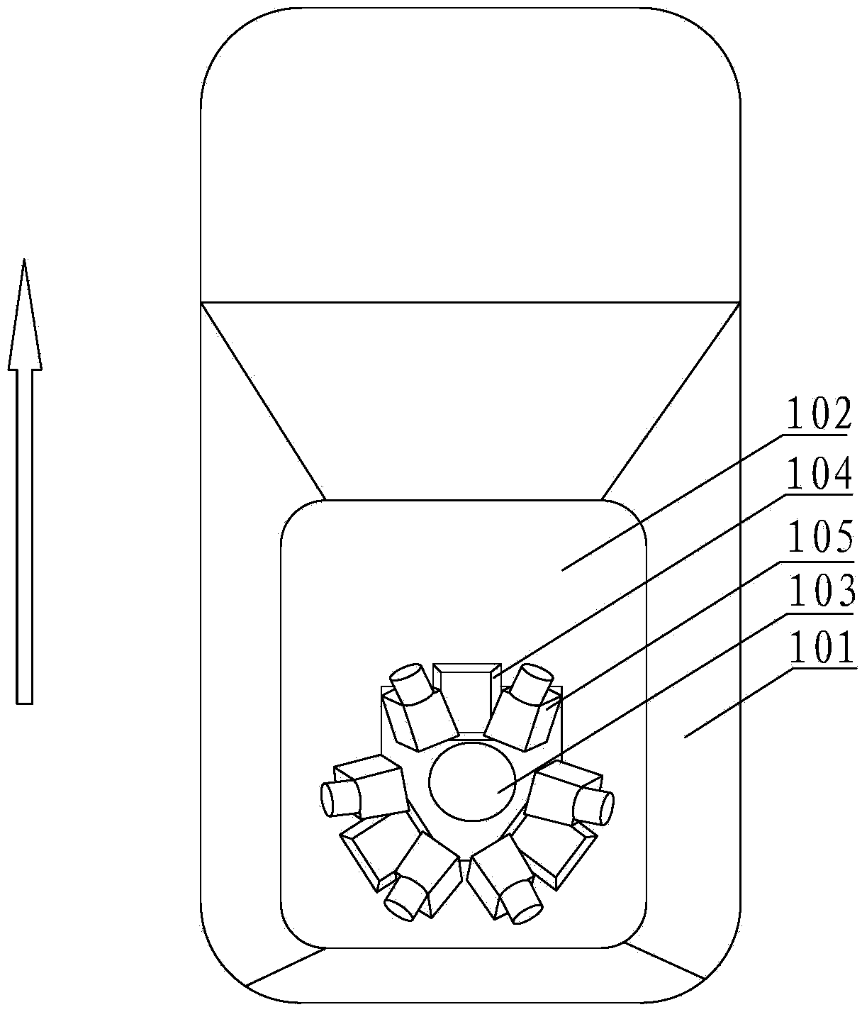
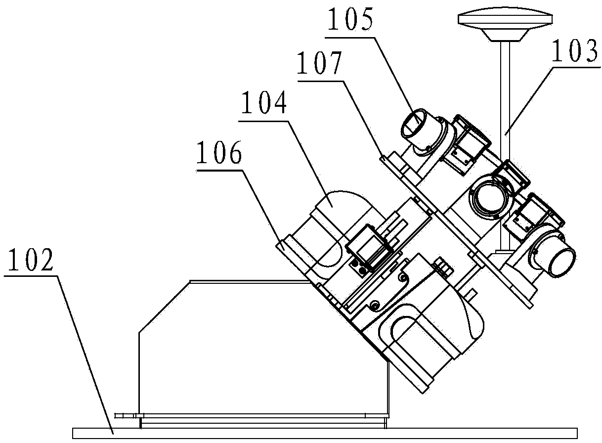
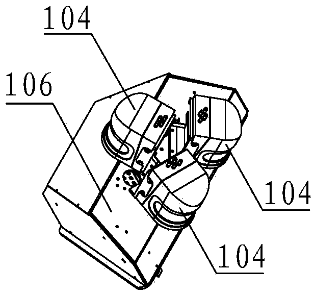
[0068] Data acquisition equipment, including GPS receivers and antennas, inertial measurement units, laser scanners, and industrial CCD cameras, used to collect raw laser point clouds, images, and GPS/INS data related to highway road condition indicators;
[0069] The data acquisition industrial computer is used to receive and store the data collected by each data acquisition device, and the industrial CCD camera is connected to the data acquisition industrial computer through a cable;
[0070] The monitoring computer is connected to the same local area network with each data acquisition device and data acquisition industrial computer through a network switch, and interacts with data and status through a custom protocol based on TCP/IP;
[0071] Synchronization controller, used to coordinate time synchronization, status response, data transmission and storage among various data acquisition devices;
[0072] Mobile power supply, as the power supply for each data acquisition equipment, monitoring computer and synchronous controller;
[0073] Mobile inspection vehicle, as a platform for data acquisition system, is used to carry various data acquisition equipment, monitoring computer, synchronization controller and mobile power supply;
[0074] The odometer, when the satellite signal is easily blocked or interfered, participates in the integrated navigation positioning solution to improve the positioning accuracy of the vehicle. In addition, the odometer is also used for equidistant acquisition control of image data and judging whether the mobile inspection vehicle is in a stopped state ;
[0075] The data processing system is equipped with a processing computer inside, which is used for data preprocessing, point cloud filtering and data analysis, road facilities and disease inspection of the original laser point cloud, image, GPS/INS data collected by the data acquisition equipment.
[0076] Specifically, such as Figure 1 to Figure 4 As shown, a measurement platform 102 is installed on the top of the mobile inspection vehicle 101, and a GPS receiver and antenna 103, an inertial measurement unit, a laser scanner 104, an industrial CCD camera 105, a synchronization controller and a network switch are respectively installed on the measurement platform 102. The data acquisition industrial computer and mobile power supply are placed in the mobile inspection vehicle, for example, in the trunk; the odometer is placed at the wheel position of the mobile inspection vehicle; each data acquisition device is connected to the network switch through cables; the power supply Cables, camera cables and monitoring cables are extended into the car from the side windows of the mobile patrol car 101, the power cable is connected to the mobile power supply, and the monitoring cable is connected to the monitoring computer, which can be a monitoring notebook, which is easy to take , Carry and operate, the operator holds the monitoring computer to complete various data collection operations. The speed of the mobile inspection vehicle 101 is not less than 60km/h, which is beneficial to ensure the normal operation of the expressway and improve the detection efficiency. figure 1 The middle arrow shows the traveling direction of the mobile inspection vehicle.
[0077] In addition, the measurement platform 102 is a horizontal measurement platform, and the measurement platform is provided with a laser scanner installation platform 106 and an industrial CCD camera installation platform 107 at an angle of 45 degrees with the measurement platform 102, and the laser scanner installation platform 106 and the industrial CCD The camera installation platforms 107 are parallel to each other; there are three laser scanners 104, which are arranged on the laser scanner installation platform 106. Specifically, the three laser scanners are just at the three vertices of an isosceles triangle whose base angle is 65 degrees. In the direction of vehicle travel, the laser scanner on the top collects point cloud data of tunnels, viaducts and expressway overhead facilities, and the scanners on the left and right sides of the tail collect point cloud data such as road surface, slope and isolation belt; there are six industrial CCD cameras 105, Arranged on the industrial CCD camera installation platform 107, specifically, six industrial CCD cameras are located on six equal points of a circle with a diameter of 420mm, and are stitched into a 360-degree panoramic image; the GPS receiver is placed in the measurement platform 102 ; The GPS antenna 103 is installed vertically on the industrial CCD camera installation platform 107.
[0078] The vehicle-mounted expressway inspection system can provide all the elements required by the expressway, and can quickly obtain three-dimensional space data and attribute data such as road components, road diseases, and road terrain, and perform rapid inspection and inspection of roadbeds, road surfaces, and road properties. Analysis provides decision-making basis for daily maintenance and management of expressways.

Example Embodiment

[0079] Example 2
[0080] A data acquisition method of a vehicle-mounted highway inspection system, using the vehicle-mounted highway inspection system in Embodiment 1, such as Figure 5 As mentioned above, the monitoring design of the data acquisition system adopts the CS architecture. One end of the monitoring computer is used as the client, and the other end of the data acquisition device is used as the server. Control commands are sent to the server through the client, and the client runs the monitoring program. Data acquisition equipment control, data acquisition, data display and status display of each data acquisition equipment.
[0081] The process of data acquisition is to use each data acquisition device and monitoring computer in the same local area network, and to exchange data and status through a custom protocol based on TCP/IP. Image 6 A frame diagram of data acquisition and storage is shown.
[0082] like Figure 7 As shown, the monitoring computer runs the monitoring program and performs interface-based operations. The data acquisition operation process includes searching for data acquisition equipment, creating projects, connecting data acquisition equipment, setting working parameters of data acquisition equipment, setting inertial measurement unit alignment parameters, and waiting , start data collection, end the project and other steps. The following describes the process of data acquisition in the form of a flow chart:
[0083] aInitialization preparation process
[0084]a1. The monitoring computer runs the monitoring program, searches for all data collection equipment service programs in the local area network, and selects the data collection equipment service program that participates in the project collection work from the searched data collection equipment service programs to start the corresponding data collection equipment;
[0085] a2. Create a project for this project collection. When creating a project, you need to enter the project name, and generate a folder corresponding to the project name on the monitoring computer to store the collected data of this project;
[0086] a3, sequentially set the working parameters of each data acquisition equipment participating in the project collection work, and set the working parameters of the synchronous controller;
[0087] The working parameter settings of the data acquisition equipment include: GPS needs to collect data records, laser scanner working parameters, industrial CCD camera working parameters;
[0088] The inertial measurement unit alignment parameter setting is used to complete the initialization of the inertial navigation system. After the alignment parameter setting is completed, the inertial navigation takes about 2 minutes to complete the coarse alignment;
[0089] After the inertial navigation completes the coarse alignment, the measurement platform has been adjusted to a certain accuracy range, and then wait for 10 to 15 minutes to perform the inertial navigation fine alignment to improve the alignment accuracy. After the fine alignment is completed, the inertial navigation enters the navigation working state ;
[0090] b data collection stored procedure
[0091] The data acquisition equipment collects the raw data of road condition indicators during the highway inspection process, and then transmits these raw data to the data acquisition industrial computer through the local area network, and stores them in the folder corresponding to this project on the data acquisition industrial computer.

Example Embodiment

[0092] Example 3
[0093] A data processing method for a vehicle-mounted highway inspection system, using the vehicle-mounted highway inspection system in Embodiment 1, the original data collected during the highway inspection process includes laser point clouds, images, and GPS/INS data. The data processing method includes the following data processing steps:
[0094] aData preprocessing
[0095] Perform data analysis, attitude calibration, format conversion and project management output on the original laser point cloud, image and GPS/INS data acquired during the highway inspection process, such as Figure 8 Shown:
[0096] GPS/INS data processing
[0097] (1) Perform differential calculation on GPS data and analyze data accuracy;
[0098] (2) Combining differential GPS data and inertial navigation data for calculation, outputting high-precision time, position and attitude information;
[0099] Laser Scanner Preprocessing
[0100] (1) Perform signal filtering and denoising on the laser point cloud according to the information recorded by the main control system;
[0101] (2) Correct the point cloud data through calibration parameters to realize point cloud splicing;
[0102] (3) Carry out spatial coordinate conversion, output the plane coordinates in the corresponding coordinate system, and save it as a standard point cloud data format at the same time;
[0103] Industrial CCD camera data preprocessing
[0104] (1) Correct the image according to the camera calibration parameters to remove the larger distortion image;
[0105] (2) Compress and thin out images according to data accuracy requirements;
[0106] True color point cloud
[0107] By fusing point clouds and images, a true-color point cloud that can express the real environment is generated, specifically:
[0108] (1) Obtain the image corresponding to the point cloud according to the time synchronization system, extract the image parameters recorded by the system at the same time, and restore the spatial position of the image;
[0109] (2) Based on the idea of ​​the collinear equation, extract the pixel points on the image corresponding to the laser point, store the color value in the point cloud data, and display the true color point cloud with color rendering;
[0110] Engineering treatment
[0111] (1) Create point cloud index and mileage index according to time;
[0112] (2) According to the requirements of the office workers and the progress of the project, the entire road section is segmented according to the mileage, processed in parallel, and the segmented point cloud and image picture are output;
[0113] b point cloud filtering and data analysis
[0114] Based on the filtering algorithm, the classification of road point cloud and slope point cloud is realized, and the road surface and slope digital elevation model, road strength orthophoto and road slope orthophoto are generated by the inverse distance weighted interpolation method, as follows:
[0115] b1. By analyzing the spatial characteristics of the laser scanning point cloud, the initial pavement and slope seed points are extracted using the spatial feature constraint method, sorted least squares slope estimation method and window iterative analysis method, and then based on the local slope filtering method, the seed points are extracted Extract all road surface point clouds and slope point clouds as reference points;
[0116] b2. Use the inverse distance weighted interpolation method to interpolate the elevation and intensity of the road surface point cloud, generate the digital elevation model of the road surface and slope, and the orthophoto image of the road surface strength, and then analyze the slope of the digital elevation model of the road surface and slope to generate the road surface slope positive shooting image;
[0117] c Road facilities and disease inspection
[0118] By analyzing the characteristics of point cloud, image and interpolation processing data, a patrol inspection method that meets the needs of expressway facilities and disease inspection is formulated, as follows:
[0119] c1. Subgrade facilities and disease inspections, superimposed by multiple acquisitions of road surface and slope digital elevation model data, analyze subgrade settlement and slope collapse, and visually interpret subgrade structure damage, water damage gullies, and road shoulders from image data Dirty gutters, damaged road shoulders, missing and straight curb stones, clogged gutters;
[0120] c2. Inspection of pavement facilities and diseases. Through image analysis of pavement images, pavement cracks, massive cracks, longitudinal cracks, and transverse cracks are identified. Through digital elevation models of pavement and slopes and slope orthophoto images, potholes, grooves, etc. are analyzed. Rutting, subsidence, and wave wrapping, analyze the road surface looseness, oil flooding, repair, falling objects, oil stains, and stagnant water through the orthophoto and real image of the road surface intensity;
[0121] c3. Road production facilities and disease inspections, visually inspect the facilities along the traffic from real-scene images, including whether the guardrails are straight, whether there are missing or rusted accessories, signs and signs, sound insulation walls, whether there are missing or damaged accessories, rusted, central Whether the anti-glare plate of the divider is missing or damaged, or rusted, and analyze whether the marking lines, contour marks, and raised road signs are defective according to the orthophoto and real-world images of the road surface strength.

PUM

no PUM

Description & Claims & Application Information

We can also present the details of the Description, Claims and Application information to help users get a comprehensive understanding of the technical details of the patent, such as background art, summary of invention, brief description of drawings, description of embodiments, and other original content. On the other hand, users can also determine the specific scope of protection of the technology through the list of claims; as well as understand the changes in the life cycle of the technology with the presentation of the patent timeline. Login to view more.

Similar technology patents

Classification and recommendation of technical efficacy words

  • Guaranteed reliability
  • Guaranteed data accuracy

Method and device for transporting message

ActiveCN106130882ASolve the congestion problemGuaranteed reliabilityData switching networksClient-sideTelemetry
Owner:BEIJING BAIDU NETCOM SCI & TECH CO LTD

Control system of pure water cooling device of high voltage direct current (HVDC) transmission converter valve

ActiveCN101634866AGuaranteed reliabilityNarrow down the scope of the accidentTemperature control without auxillary powerExchange of informationControl system
Owner:GUANGZHOU GOALAND ENERGY CONSERVATION TECH
Why Eureka
Try Eureka