Sliding type friction nanometer generating set

A generator set, sliding technology, applied in the direction of friction generators, etc., can solve the problems of large size, complex structure, and inability to use power supply components of microelectronic devices, etc., and achieve the effects of small size, low cost and simple structure

Active Publication Date: 2014-05-07
BEIJING INST OF NANOENERGY & NANOSYST
View PDF4 Cites 29 Cited by
  • Summary
  • Abstract
  • Description
  • Claims
  • Application Information

AI Technical Summary

Problems solved by technology

These generators all require relatively concentrated and high-intensity energy input, and it is basically impossible to effectively convert the kinetic energy of low intensity generated in people's daily activitie

Method used


Image

  • Sliding type friction nanometer generating set
  • Sliding type friction nanometer generating set
  • Sliding type friction nanometer generating set

Examples


Embodiment 1

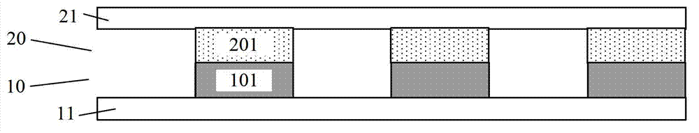
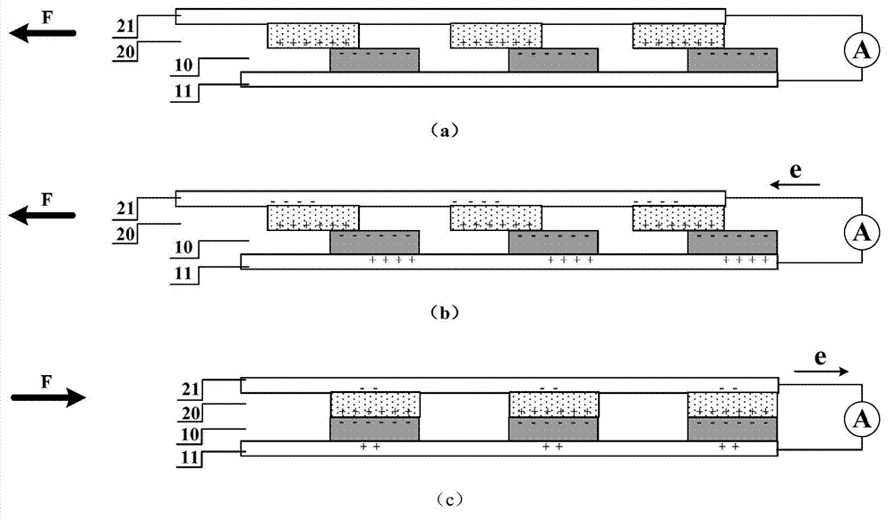
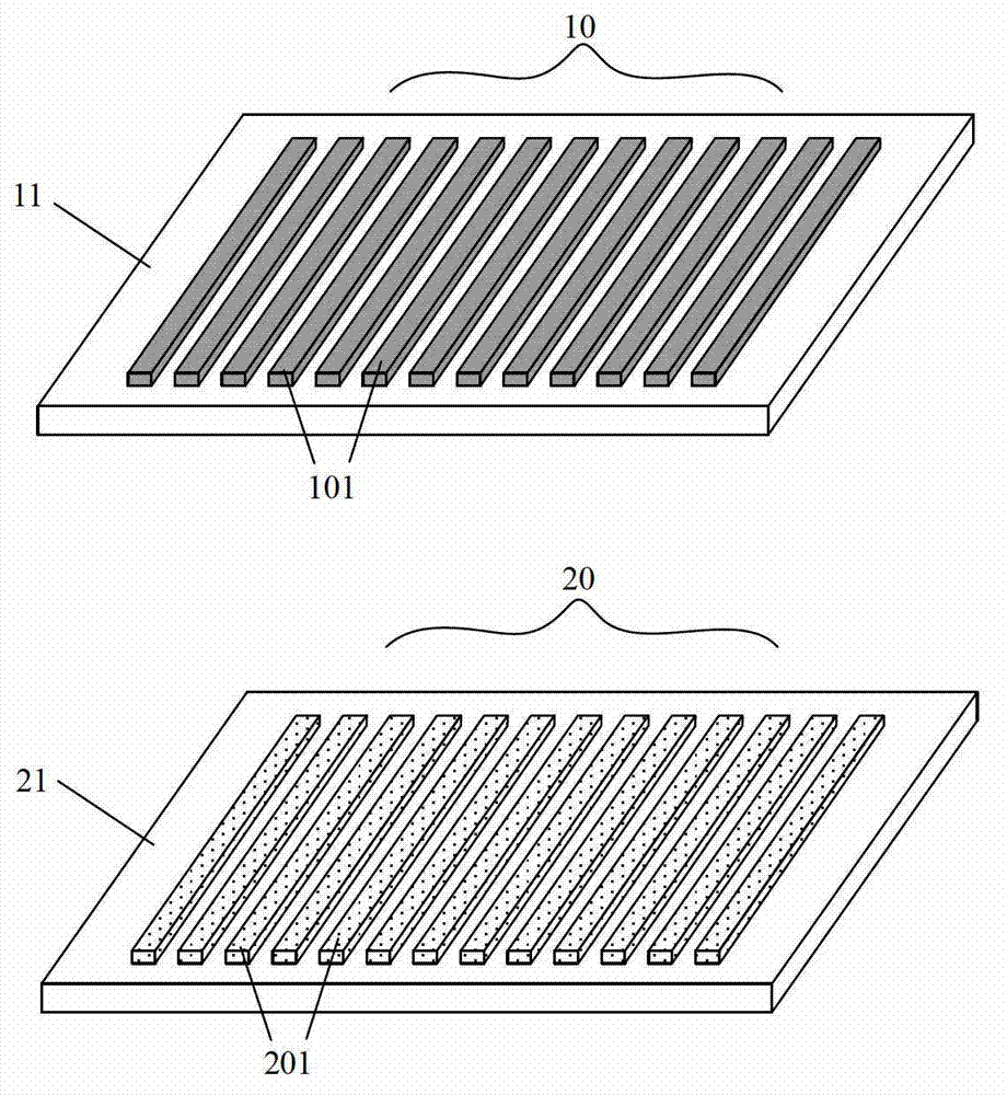
[0098] The first conductive element is a metal copper sheet with a thickness of 1mm and a size of 5cm×6cm. The second conductive element is a metal aluminum sheet with the same size. The material of the first friction unit is Teflon (polytetrafluoroethylene) film. The material of the two friction units is polyethylene terephthalate (PET). Polytetrafluoroethylene and polyethylene terephthalate have extremely negative and extremely positive polarities, respectively, in the triboelectric series. Teflon is made into a strip film structure with length, width and height of 5cm, 0.5cm and 0.2cm respectively, and according to image 3 distributed on the copper sheet at intervals of 0.5 cm. Polyethylene terephthalate is made into a strip film structure with a length, width and height of 5cm, 0.5cm and 0.2cm, and is also distributed on the aluminum sheet at an interval of 0.5cm.

[0099] After the wires are drawn out on the metal aluminum sheet and the metal copper sheet, the polyethy...

Embodiment 2

[0101] This embodiment is basically the same as Embodiment 1, the only difference is that: a silicon wafer with a thickness of 600 μm is used as the first friction unit material, and a layer of photoresist is coated on the surface of the silicon wafer by rotation A square window array with a side length of micron or sub-micron level is formed on the glue, and the silicon wafer after photolithography is chemically etched with hot potassium hydroxide to form a pyramid-shaped concave structure array at the window. Then divide it into small pieces with a length of 2cm and a width of 2cm, and arrange them on the surface of the first conductive element in a checkerboard shape; with polydimethylsiloxane (PDMS) as the second friction unit, it is also divided into 2cm×2cm The small pieces are arranged on the surface of the second conductive element in a manner corresponding to the silicon chip. When the silicon wafer and PDMS are in contact with each other under the action of external ...

Embodiment 3

[0103] This embodiment is basically the same as Embodiment 2, except that the nanowire array is further prepared by inductively coupled plasma etching on the PDMS surface. Put the PDMS film into an inductively coupled plasma etching machine, etch the side on which gold is deposited, and pass O 2 , Ar and CF 4 Gas, the flow rate is controlled at 10sccm, 15sccm and 30sccm respectively, the pressure is controlled at 15mTorr, the working temperature is controlled at 55°C, the plasma is generated with a power of 400 watts, and the plasma is accelerated with a power of 100 watts for about 5 minutes of etching , a PDMS nanorod array with a length of approximately 1.5 microns substantially perpendicular to the film layer was obtained. The contact area between the PDMS film with a microstructure on the surface and the silicon wafer is further increased, and the output performance of the generator is further improved.


PUM

PropertyMeasurementUnit
Lengthaaaaaaaaaa
Thicknessaaaaaaaaaa
Thicknessaaaaaaaaaa

Abstract

This invention provides a sliding type friction nanometer generating set, comprising a first conducting member, a first friction layer, a second conducting member, and a second friction layer, wherein the first friction layer is positioned in contact with the upper surface of the first conducting member and the second friction layer is positioned in contact with the lower surface of the second conducting member. The first friction layer comprises a plurality of first friction units; the second friction layer comprises a plurality of second friction units. The upper surfaces of the first friction units and the lower surfaces of the second friction units produce relative sliding friction under the action of the external force, the friction area is changed and the electric signals are outputted to the external circuit through the first conducting member and the second conducting members. In the friction nanometer generating set, when the periodic external force is applied on the basal plate of the generating set, the AC pulse signal output can be formed between a first conducting basal plate and a second conducting basal plate. The sliding type friction nanometer generating set can be used as a novel energy technology and can also be used as sensor technology.

Description

technical field [0001] The invention relates to a generator set, in particular to a sliding friction nanometer generator set which converts the mechanical energy of applied external force into electric energy. Background technique [0002] Today, with the rapid development of microelectronics and material technology, a large number of new microelectronic devices with multiple functions and high integration have been developed continuously, and have shown unprecedented application prospects in various fields of people's daily life. However, the research on the power supply system matched with these microelectronic devices is relatively lagging behind. Generally speaking, the power supply of these microelectronic devices all comes from batteries directly or indirectly. Batteries are not only large in size and heavy in weight, but also contain toxic chemical substances that are potentially harmful to the environment and the human body. Therefore, it is of great significance to...

Claims


Application Information

Patent Timeline
IPC IPC(8): H02N1/04
Inventor 王中林朱光
Owner BEIJING INST OF NANOENERGY & NANOSYST
Why Eureka
Try Eureka