
Pulse laser coherent wind measuring radar

A technology of pulsed laser and coherent wind measurement, which is applied in the direction of measurement devices, radio wave measurement systems, electromagnetic wave re-radiation, etc., can solve the problems of affecting measurement accuracy, signal misjudgment, and difficult processing, etc., to increase measurement accuracy and system Reliable and stable, improve the effect of signal-to-noise ratio

Inactive Publication Date: 2014-05-28
SOUTH WEST INST OF TECHN PHYSICS
View PDF4 Cites 38 Cited by
  • Summary
  • Abstract
  • Description
  • Claims
  • Application Information

AI Technical Summary

Problems solved by technology

Its optical path adopts the traditional multi-mirror space transmission structure, and it is difficult to adjust the optical path. Each optical lens needs to use components with the same polarization direction as the laser, which is difficult to process, high in manufacturing cost, and expensive.
In addition, when it detects at a long distance, because the echo signal is weak, it adopts the method of directly converting the optical signal into an electrical signal and then processing it, which will cause a low signal-to-noise ratio and easily lead to signal misjudgment or loss. Affect measurement accuracy

Method used

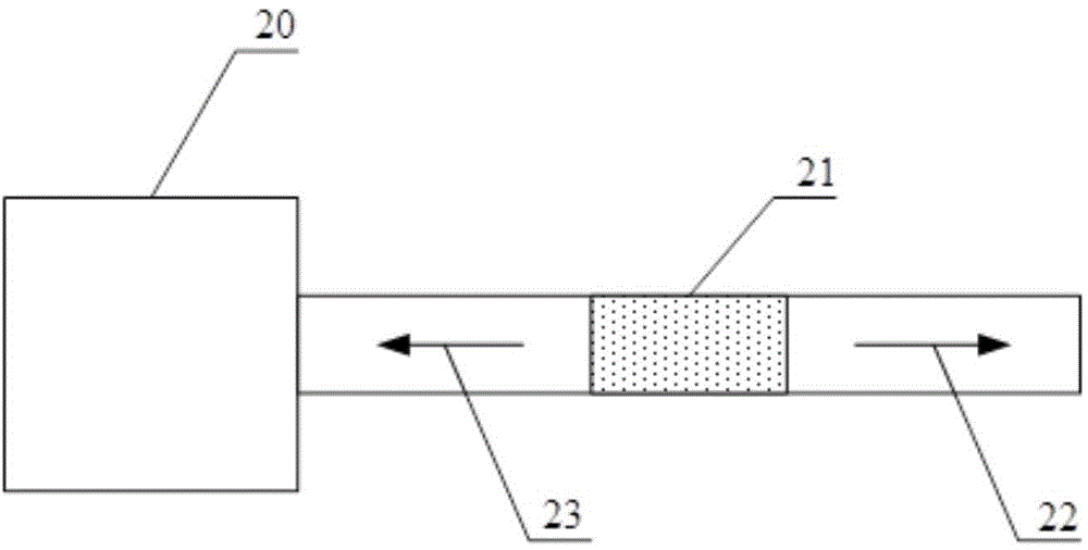
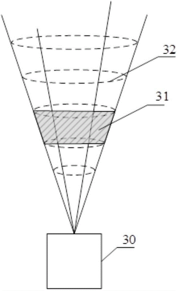

Image

  • Pulse laser coherent wind measuring radar
  • Pulse laser coherent wind measuring radar
  • Pulse laser coherent wind measuring radar

Examples


Embodiment Construction

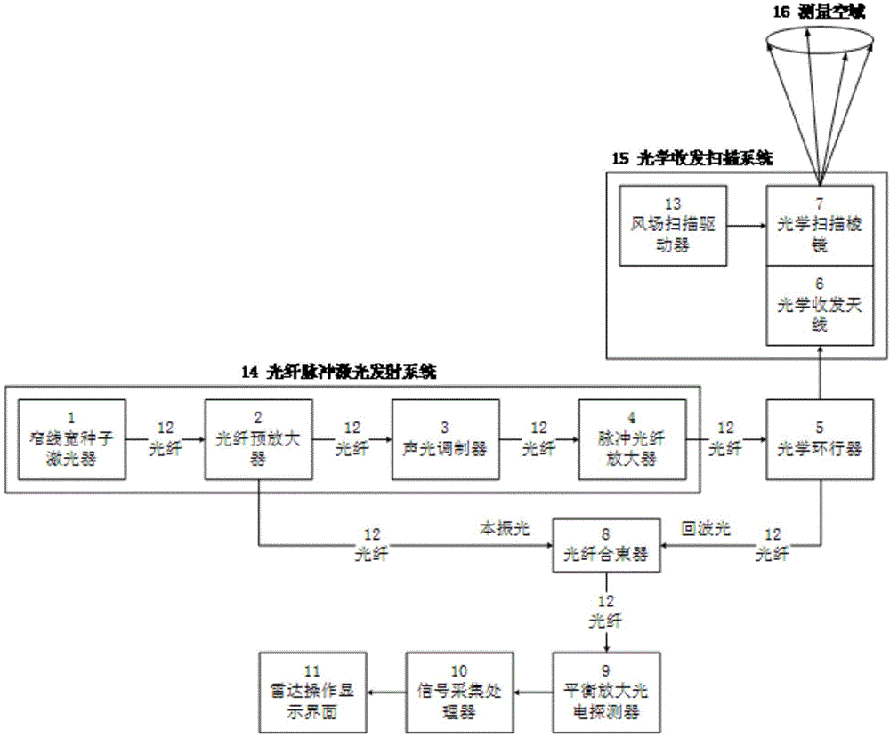
[0014] refer to figure 1 . In a preferred embodiment described below, the pulsed laser coherent wind radar mainly includes a fiber optic pulsed laser emission system 14, an optical circulator 5, an optical transceiver scanning system 15, an optical fiber beam combiner 8, a balanced photodetector 9, a signal An acquisition processor 10 and a radar operation display interface 11 . The fiber pulsed laser emission system 14 is composed of a narrow linewidth seed laser 1 , a fiber preamplifier 2 , an acousto-optic modulator 3 and a pulsed fiber amplifier 4 connected in series. The optical circulator 5 is composed of a polarization beam splitting prism and a quarter wave plate. The optical transceiving scanning system 15 is composed of an optical scanning prism 7 connected to a wind field scanning driver 13 and an optical transceiving antenna 6 . The rotational movement state of the optical scanning prism 7 is controlled by the wind field scanning driver 13 , and the wind field s...


PUM


Abstract

The invention brings forward a pulse laser coherent wind measuring radar, for the purpose of providing a pulse laser coherent wind measuring radar which has the advantages of high measuring precision, simple structure and convenient installation and debugging. The pulse laser coherent wind measuring radar is realized through the following technical scheme: a fiber pulse laser emission system is taken as an emission source for generating two beams of laser, one beam of high repetition frequency pulse sequence laser for wind field detection is directly coupled through an optical circulator and enters an optical transmit-receive scanning system to perform collimated emission towards a target spatial domain, the optical circulator utilizes a polarization splitting characteristic to carry out isolation splitting on emission light and air aerosol scattering echo wave light, the air aerosol scattering echo wave light is selected to enter a fiber combiner, the other beam of laser, generated by the fiber pulse laser emission system, is taken as local oscillator light for inputting into a balance amplification photoelectric detector together with the echo wave light in a frequency mixing mode for optical amplification of a frequency mixing signal, through acquisition processing of a signal acquisition processor, the radial speed of each range gate in a current laser emission direction is calculated, and the radial speeds are transmitted to a radar operation display interface.

Description

technical field [0001] The invention relates to a pulse laser coherent wind measuring radar used for measuring wind speed and direction of medium and long-distance atmospheric wind fields. More specifically, the present invention relates to an integrated, modular mid-range and long-range wind-measuring lidar that utilizes the laser Doppler effect and the principle of coherent detection, adopts all-fiber connection transmission, and combines the transmitting and receiving antennas into one. Background technique [0002] The radar system used to measure the wind speed and direction of the atmospheric wind field in the prior art measures the atmospheric wind field by using the Doppler frequency shift effect of the scattered echoes of laser light by tiny particles drifting with the wind in the atmosphere. Generally, a coherent detection method with the characteristics of no need for direct contact, high measurement accuracy, and long operating distance is also used. For example...

Claims


Application Information

Patent Timeline
IPC IPC(8): G01S17/95
CPCG01S7/486G01S17/95Y02A90/10
Inventor 周鼎富伍波赵彬杨泽后罗雄冯立天陈涌樊冬
Owner SOUTH WEST INST OF TECHN PHYSICS
Learn More