Laser and MIG electric arc compound welding method for high-strength steel butt joints

A butt joint and composite welding technology, which is applied to laser welding equipment, welding equipment, welding/welding/cutting items, etc., can solve the problems of high assembly conditions, low efficiency of MIG welding, insufficient welding thickness, etc., and reduce assembly conditions Requirements, good weld performance and low assembly requirements

Inactive Publication Date: 2014-06-04
BEIJING HANGXING MACHINERY MFG CO LTD
View PDF8 Cites 16 Cited by
  • Summary
  • Abstract
  • Description
  • Claims
  • Application Information

AI Technical Summary

Problems solved by technology

[0004] The technical solution of the present invention is to provide a laser-MIG arc composite welding method for high-strength steel butt joints, which solves the high requirements for high-strength steel welding laser welding assembly conditions, low MIG welding efficiency, easy cracks in the weld seam, and insufficient thickness of laser welding alone. and other shortcomings, this method can improve the welding penetration without increasing the YAG laser power, adapt to wider assembly conditions, improve the welding quality, and obtain good welding performance

Method used


Image

  • Laser and MIG electric arc compound welding method for high-strength steel butt joints
  • Laser and MIG electric arc compound welding method for high-strength steel butt joints

Examples


Embodiment 1

[0030] 1) 30CrMnSi material 2mm thick structural plate butt welding

[0031] The specific steps are:

[0032] The first step: the high-strength steel joint to be welded is processed into an I-shaped groove, and the joint form is a butt joint;

[0033] Step 2: Assemble the joint to be welded, and control the assembly gap of the joint to not exceed 0.1δ;

[0034] Step 3: Select a welding wire with a diameter of 1.6mm, and perform pre-welding treatments such as degreasing, pickling, drying, and sandblasting on the weldment and the welding wire. The welding wire can also be bright welding wire without cleaning;

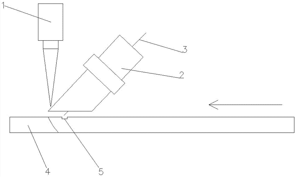
[0035] Step 4: Arrange the laser and MIG heat source: the laser beam is incident vertically 2 mm in front of the MIG, and the welding wire is sent to the upper surface of the workpiece through the MIG gun nozzle at an angle of 30° to the horizontal plane; ensure that the two heat sources form a common molten pool together, The welding wire is sent to the upper surface o...

Embodiment 2

[0040] 2) 30CrMnSi material 5mm thick structural plate butt welding

[0041] The specific steps are:

[0042] The first step: the high-strength steel joint to be welded is processed into an I-shaped groove, and the joint form is a butt joint;

[0043] Step 2: Assemble the joint to be welded, and control the assembly gap of the joint to not exceed 0.1δ;

[0044] Step 3: Select a welding wire with a diameter of 1.6mm, and perform pre-welding treatments such as degreasing, pickling, drying, and sandblasting on the weldment and the welding wire. The welding wire can also be bright welding wire without cleaning;

[0045] Step 4: Arrange the laser and MIG heat source: the laser beam is incident vertically 2 mm in front of the MIG, and the welding wire is sent to the upper surface of the workpiece through the MIG gun nozzle at an angle of 45° to the horizontal plane; ensure that the two heat sources form a common molten pool together, The welding wire is sent to the upper surface o...

Embodiment 3

[0050]3) 30CrMnSi material 7mm thick structural cylindrical butt welding

[0051] The specific steps are:

[0052] The first step: the high-strength steel joint to be welded is processed into an I-shaped groove, and the joint form is a butt joint;

[0053] Step 2: Assemble the joint to be welded, and control the assembly gap of the joint to not exceed 0.1δ;

[0054] Step 3: Select a welding wire with a diameter of 1.6mm, and perform pre-welding treatments such as degreasing, pickling, drying, and sandblasting on the weldment and the welding wire. The welding wire can also be bright welding wire without cleaning;

[0055] Step 4: Arrange the laser and MIG heat source: the laser beam is incident vertically from 3 mm in front of the MIG, and the welding wire is sent to the upper surface of the workpiece through the MIG gun nozzle at an angle of 60° to the horizontal plane; ensure that the two heat sources form a common molten pool together, The welding wire is sent to the upper...


PUM

PropertyMeasurementUnit
diameteraaaaaaaaaa
diameteraaaaaaaaaa

Abstract

The invention discloses a laser and MIG electric arc compound welding method for high-strength steel butt joints. The laser and MIG electric arc compound welding method comprises the specific steps that (1) high-strength steel butt joints to be welded are machined to be provided with I-shaped grooves, wherein the high-strength steel butt joints are of a butt joint form; (2) the high-strength steel butt joints to be welded are assembled, and the size of an assembly gap between the high-strength steel butt joints is controlled to be smaller than or equal to 0.1delta; (3) welding wires are selected according to the materials of the high-strength steel butt joints to be welded, and pre-welding treatment such as oil removal, acid pickling, drying and sand blasting is carried out on the high-strength steel butt joints to be welded and the welding wires; (4) a laser source and an MIG thermal source are arranged, wherein a laser beam is perpendicularly incident from the position which is one to three millimeters away from the front portion of the MIG thermal source, the welding wires are fed into the upper surface of the high-strength steel butt joints to be welded through an MIG muzzle, and the angle between each welding wire and the horizontal plane ranges from 30 degrees to 60 degrees; (5) laser beam and MIG compound welding is carried out, and in an initial period, the maintenance time of lasers and the maintenance time of an electric arc range from 0 s to 0.5 s. The laser and MIG electric arc compound welding method for the high-strength steel butt joints, welding penetration is improved, the requirement for assembly conditions is reduced, welding quality is improved, and high welding performance is achieved.

Description

technical field [0001] The invention belongs to the technical field of laser welding, and relates to a laser-MIG arc composite welding method for high-strength steel butt joints. Background technique [0002] High-strength steel is one of the metal materials widely used in pressure vessels, bridges, ships, aerospace and other fields. It has high strength, good plasticity and toughness. Due to the high-strength steel alloy elements, high carbon content, and large hardening tendency, it is determined that the welding method with concentrated heat should be used when welding. Laser welding is very suitable for welding high-strength steel due to its advantages of high energy density, high efficiency, high precision, and strong adaptability. The laser-MIG hybrid welding technology in laser welding technology combines the advantages of laser welding and MIG welding organically, which can not only reduce the requirements for the assembly accuracy of welded parts, but also make up ...

Claims


Application Information

Patent Timeline
Patent Type & Authority Applications(China)
IPC IPC(8): B23K28/02
CPCB23K2103/50B23K26/32B23K26/348B23K26/60B23K2103/04
Inventor 王志敏蒋海涛陈久友姚为汪永阳张铁军李宏伟
Owner BEIJING HANGXING MACHINERY MFG CO LTD
Why Eureka
Try Eureka