A Limiting Amplifier with On-chip DC Offset Cancellation

A limiting amplifier and DC offset technology, applied in power amplifiers, improved amplifiers to reduce temperature/power supply voltage changes, etc., can solve the problem of increasing the low-pass filter of the DC negative feedback network, difficult to achieve capacitor area, and output drift, etc. problem, to achieve excellent performance, eliminate DC offset, low and low frequency cut-off frequency effect

Active Publication Date: 2017-02-01
JIAXING HEROIC ELECTRONICS TECH
View PDF4 Cites 0 Cited by
  • Summary
  • Abstract
  • Description
  • Claims
  • Application Information

AI Technical Summary

Problems solved by technology

While stabilizing the DC level of the circuit, the DC negative feedback network introduces a low-frequency cut-off frequency to the AC characteristics of the circuit. Too high a low-frequency cut-off frequency will cause the output terminal to be amplified when the continuous "1" or continuous "0" is amplified. Drift occurs, which eventually leads to bit errors
In order to overcome this problem, the value of the resistance and capacitance of the low-pass filter in the DC negative feedback network is usually increased, but the capacitance area is too large to be realized on-chip, so the traditional method is to use an off-chip capacitor

Method used


Image

  • A Limiting Amplifier with On-chip DC Offset Cancellation
  • A Limiting Amplifier with On-chip DC Offset Cancellation
  • A Limiting Amplifier with On-chip DC Offset Cancellation

Examples


Embodiment Construction

[0034]Below in conjunction with accompanying drawing, the embodiment of the present invention is described in detail: present embodiment implements under the premise of the technical scheme of the present invention, has provided detailed implementation and specific operation process, but protection scope of the present invention is not limited to the following the embodiment.

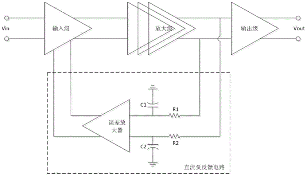
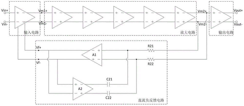
[0035] A schematic diagram of the specific circuit operation of a limiting amplifier that realizes the DC offset elimination function on a chip of the present invention is as follows: figure 2 Shown, including input circuit, amplifier circuit, output circuit and DC negative feedback circuit.

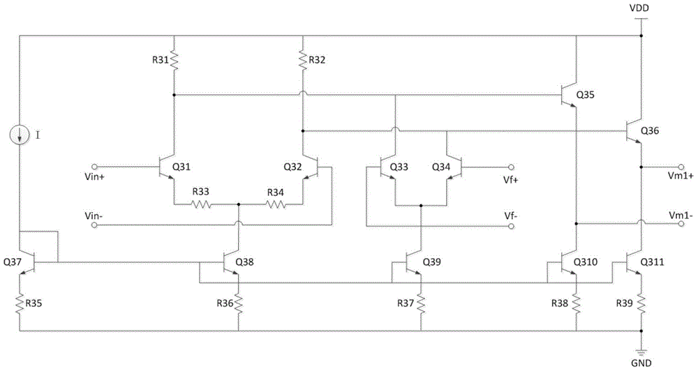
[0036] The circuit diagram of the input circuit is as follows image 3 , including a current mirror array composed of transistors Q37, Q38, Q39, Q310, Q311 and resistors R35, R36, R37, R38, R39, transistors Q31, Q32, load resistors R31, R32, and emitter negative feedback resistors R33, R34 A differential amplif...


PUM


Abstract

The invention discloses a limiting amplifier allowing a direct-current offset eliminating function to be achieved on a sheet. The limiting amplifier comprises an input circuit, an amplifying circuit, an output circuit and a direct-current negative feedback circuit. The direct-current negative feedback circuit comprises a first amplifier, a second amplifier, a first capacitor, a second capacitor, a first resistor and a second resistor. The first amplifier, the second amplifier, the first capacitor and the second capacitor form a closed loop. Direct-current offset of the amplifying circuit is fed back to the input circuit to be used for eliminating direct-current offset of the circuits after being sampled through a low-pass filter formed by the first resistor, the second resistor, the first capacitor and the second capacitor of the direct-current feedback circuit, and amplified through the first amplifier. According to the limiting amplifier, a direct-current offset eliminating circuit is obtained through the small capacitors on the sheet, and the phenomenon that error codes are produced when low-frequency cut-off frequency is excessively high due to the direct-current offset eliminating circuit can not occur even when a long string of 1 signals or a long string of 0 signals are processed.

Description

technical field [0001] The invention relates to a limiting amplifier applied in the field of optical communication, in particular to a limiting amplifier with high gain bandwidth and on-chip DC offset elimination function. Background technique [0002] With the rapid development of computer network, the wide application of multimedia communication and the large-scale construction of information superhighway, people's demand for high-speed communication system is getting higher and higher. Passive optical network has become the most attractive solution because of its high bandwidth, low cost, anti-interference and other advantages. As an important part of the optical receiver, the limiting amplifier's main function is to further amplify the smaller voltage signal provided by the pre-stage transimpedance amplifier for use by the post-stage clock recovery circuit. [0003] figure 1 Shown is a traditional limiting amplifier, mainly consisting of an input stage, multiple gain s...

Claims


Application Information

Patent Timeline
Patent Type & Authority Patents(China)
IPC IPC(8): H03F1/30H03F3/20
Inventor 邵思佳王清鹏王良坤殷明
Owner JIAXING HEROIC ELECTRONICS TECH
Why Eureka
Try Eureka