
Flow battery

A liquid flow battery and flow channel technology, applied in fuel cells, battery electrodes, regenerative fuel cells, etc., can solve the problems of strong corrosion, high price, and affecting the life of liquid flow batteries, so as to improve the service life and reduce the price , the effect of reducing cost pressure

Inactive Publication Date: 2014-06-18
POSITEC POWER TOOLS (SUZHOU) CO LTD +1
View PDF8 Cites 4 Cited by
  • Summary
  • Abstract
  • Description
  • Claims
  • Application Information

AI Technical Summary

Problems solved by technology

However, the alkaline zinc-nickel flow battery has a strong alkaline electrolyte, which is highly corrosive and affects the life of the flow battery.
And the positive electrode is a nickel electrode, which is more expensive, which is not conducive to reducing the cost of large-scale energy storage

Method used


Image

  • Flow battery

Examples


preparation example Construction

[0046] The preparation process of the positive electrode is preferably to stir and mix the positive electrode active material, positive electrode conductive agent and binder in a solvent in a certain proportion to obtain the required positive electrode slurry, then apply the positive electrode slurry on the positive electrode current collector, and dry , Tablet treatment to obtain the positive electrode.

[0047] The solvent used in the positive electrode slurry in the present invention can be selected from conventionally used solvents in the field, such as N-methylpyrrolidone (NMP), N,N-dimethylformamide (DMF), N,N- One or more of diethylformamide (DEF), dimethyl sulfoxide (DMSO), tetrahydrofuran (THF), water and alcohols. The amount of the solvent is such that the positive electrode slurry can be coated on the current collector. Generally, the amount of the solvent is such that the concentration of the positive electrode active material in the positive electrode slurry is 4...

Embodiment 1

[0066] Mix crystalline α-manganese dioxide (average particle size 500nm) with conductive agent acetylene black and binder PTFE (polytetrafluoroethylene) in a mass ratio of 60:30:10, and then coat it on stainless steel plate, dried and compacted to form the positive electrode.

[0067] A zinc plate is used as the negative electrode.

[0068] ZnSO 4 Configured as Zn for electrolyte salt 2+ Electrolyte with a concentration of 1mol / L.

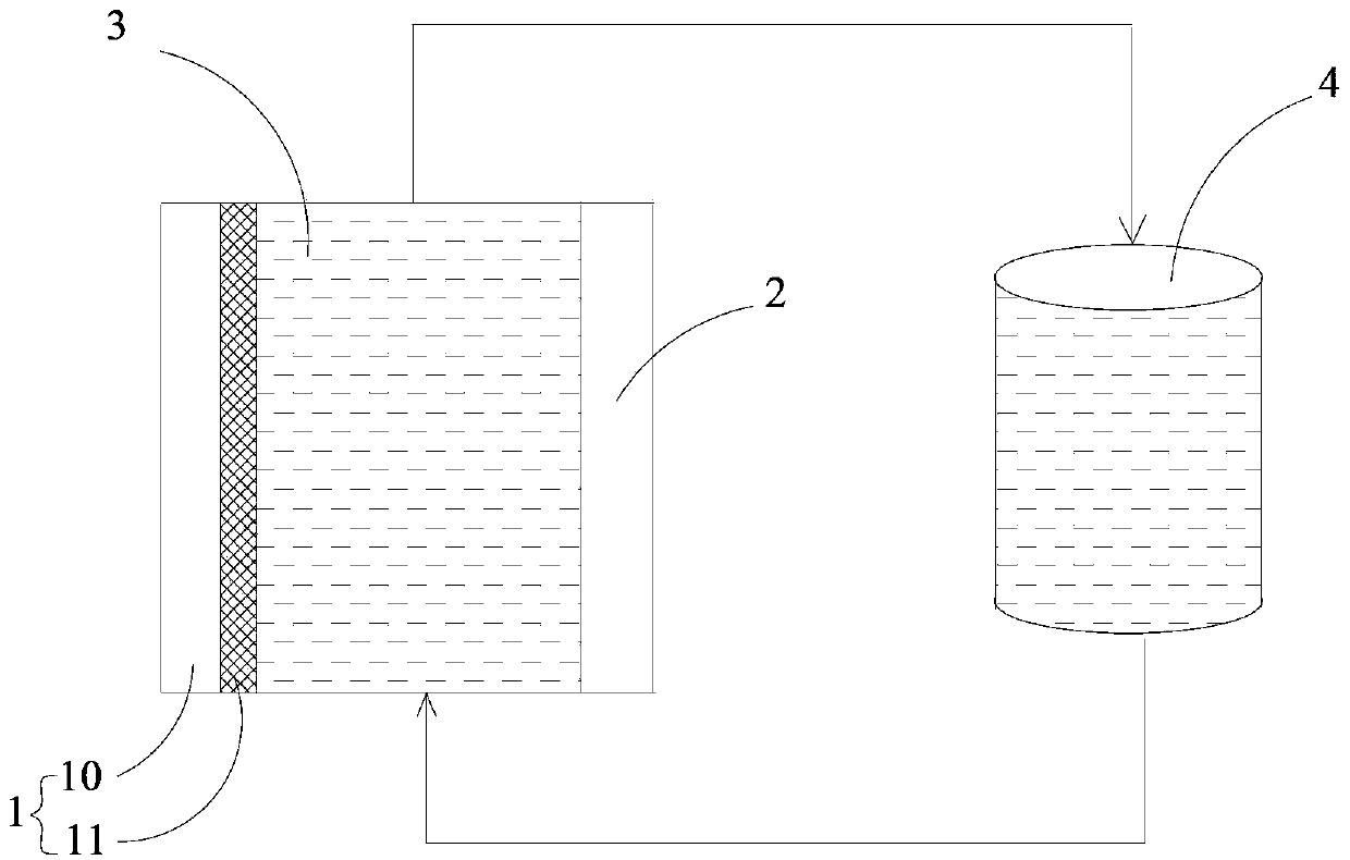
[0069] Put the positive electrode and the negative electrode into the battery case in a positive and negative manner, reserve a certain distance between the positive electrode and the negative electrode to form an electrolyte flow channel, and the electrolyte flow channel is connected to the electrolyte storage tank through the pipeline. A liquid flow pump is provided to promote the flow of electrolyte.

Embodiment 2

[0071] The difference from Example 1 is: use amorphous α-manganese dioxide instead of crystalline α-manganese dioxide, and use zinc alloy plate instead of zinc plate. Other parts are with embodiment 1.


PUM

PropertyMeasurementUnit
particle sizeaaaaaaaaaa
particle diameteraaaaaaaaaa
particle sizeaaaaaaaaaa

Abstract

The invention belongs to the field of batteries, and particularly discloses a flow battery. The flow battery includes an anode, a cathode, an electrolyte solution flow passage located between the anode and the cathode, an electrolyte solution flowing through the electrolyte solution flow passage, and an electrolyte solution storage tank for storing the electrolyte solution; the anode comprises an anode current collector and an anode active material loaded on the anode current collector; the anode active material includes a material having a Zn<2+> de-intercalation function; the cathode is zinc, a zinc alloy, a carbon electrode or an inert metal electrode; the working ion of the electrolyte solution is Zn<2+>. The flow battery provided by the invention allows the electrolyte solution to be neutral or weakly acid, thereby preventing electrolyte solution corrosion, and improving the service life; and moreover, the price is cheap. In addition, both the anode active material and the electrolyte solution are both non-toxic, low in cost, abundant in nature reserve volume, and friendly to the environment.

Description

technical field [0001] The invention belongs to the field of batteries, in particular to a liquid flow battery. Background technique [0002] Since the concept of liquid flow battery was proposed in 1974, it has attracted widespread attention due to its many advantages. [0003] Liquid flow battery is different from the solid active material contained in the positive or negative electrode of the usual storage battery. In the liquid flow battery, two oxidation-reduction pairs of high and low potential are used as the active material, and two or one of them are dissolved in the storage battery. In the electrolyte in the liquid tank, the pump makes the electrolyte flow through the inert solid electrode, and oxidation and reduction reactions occur on the surface of the inert solid electrode. Flow batteries can be divided into redox flow batteries (all-vanadium flow batteries, vanadium-iron flow batteries, sodium polysulfide / bromine flow batteries, etc.) and precipitation flow b...

Claims


Application Information

Patent Timeline
Patent Type & Authority Applications(China)
IPC IPC(8): H01M8/18H01M8/02H01M4/86
CPCY02E60/528H01M8/188Y02E60/50
Inventor 陈璞
Owner POSITEC POWER TOOLS (SUZHOU) CO LTD
Learn More