A radiator based on Stirling engine

A Stirling engine and radiator technology, applied in the direction of machines/engines, hot gas variable displacement engine devices, electrochemical generators, etc., can solve the problems that the device is only applicable and the thermal kinetic energy radiator is not applicable, and is beneficial to Recycling, saving output power, and maintaining temperature stability

Active Publication Date: 2016-03-02
DALIAN INST OF CHEM PHYSICS CHINESE ACAD OF SCI
View PDF5 Cites 0 Cited by
  • Summary
  • Abstract
  • Description
  • Claims
  • Application Information

AI Technical Summary

Problems solved by technology

Although the heat of the fuel cell is utilized, this device is only suitable for fuel cells with high temperature and catalytic combustion of fuel exhaust gas
[0005] In general, thermal kinetic energy radiators for cooling electronic components such as chipsets are not suitable for fuel cell systems, and there are many limitations in the way of combining Stirling engines and fuel cells

Method used


Image

  • A radiator based on Stirling engine
  • A radiator based on Stirling engine
  • A radiator based on Stirling engine

Examples


Embodiment 1

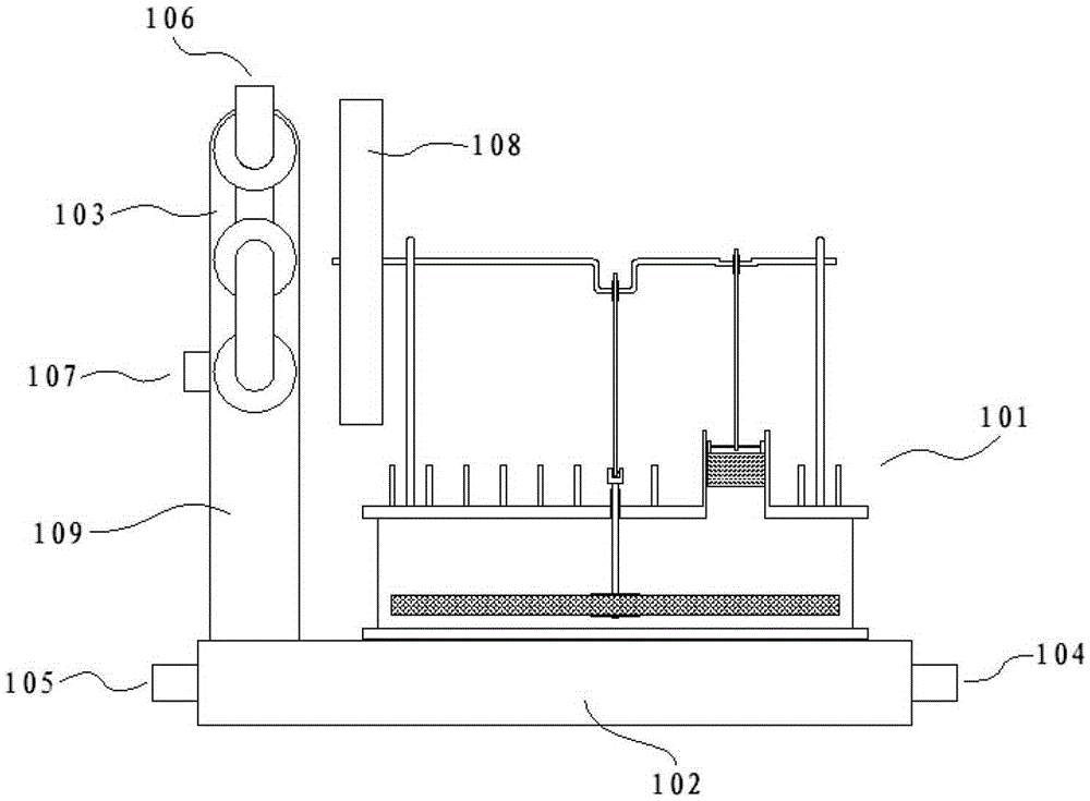
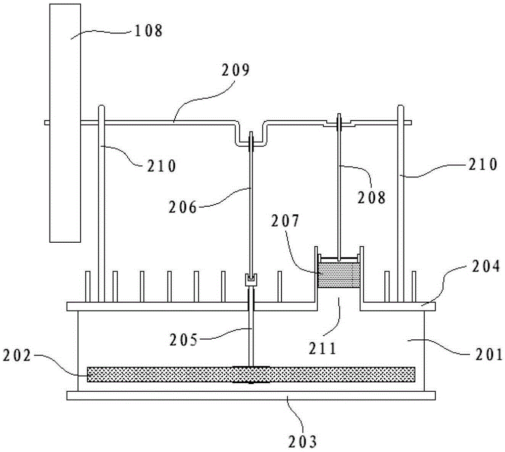
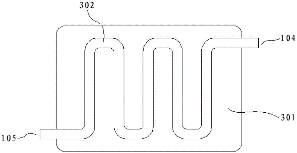
[0028] In a 100W DMFC system, the operating temperature of the fuel cell stack is about 72°C. The anode material of the fuel cell stack is methanol solution, and the temperature of the methanol solution is approximately equal to the temperature of the fuel cell stack during normal operation. Driven by the circulation pump, the methanol solution flows out from the anode outlet of the stack and enters the heat exchanger 102 through the heat exchanger material inlet 104 . When the methanol solution flows through the material channel 302 of the heat exchanger, heat is transferred to the heat conducting plate 301 , and then flows into the next component through the material outlet 105 of the heat exchanger. The heat conducting plate 301 transfers heat to the Stirling engine 101 above. Stirling engine 101 drives flywheel 108 to rotate. Driven by the air pump, water vapor, carbon dioxide, unreacted waste gas, etc. from the cathode outlet of the fuel cell stack enter the cathode mat...

Embodiment 2

[0030]In a hydrogen-oxygen fuel cell system with a power of 25kW cooling water circulation, the anode material is hydrogen, the cathode material is air, the working temperature of the fuel cell stack is about 72°C, and the cooling water circulation is used to maintain heat balance. The cooling water enters the heat exchanger 102 from the fuel cell stack cooling water outlet through the heat exchanger material inlet 104 driven by the cooling water pump. When the cooling water flows through the material channel 302 of the heat exchanger, heat is transferred to the heat conducting plate 301 , and then flows into the next component through the material outlet 105 of the heat exchanger. The heat conducting plate 301 transfers heat to the Stirling engine 101 above. Stirling engine 101 drives flywheel 108 to rotate. Driven by the air pump, cathode materials such as water vapor and unreacted waste gas from the cathode outlet of the fuel cell stack enter the cathode material radiator ...


PUM


Abstract

A Stirling engine based radiator comprises a Stirling engine, a heat exchanger and a cathodic material radiator. The heat exchanger transmits heat to the Stirling engine; the Stirling engine converts heat energy into kinetic energy to drive a flywheel to rotate; vanes on the flywheel generate air flow to assist the cathodic material radiator in radiating. When the Stirling engine based radiator is applied to a direct liquid fuel cell system, heat carried by material discharged from a cathodic outlet of an electric pile is used to radiate for the material discharged from a cathode of the electric pile. When the Stirling engine based radiator is applied to an oxy-hydrogen proton exchange membrane fuel cell system, heat carried by cooling water of the electric pile is used to radiate for the material discharged from the cathode of the electric pile. The use of the Stirling engine based radiator is good for recovery of fuel cell pile cathode water, and electric energy can be saved.

Description

technical field [0001] The invention relates to a radiator, specifically a radiator based on a Stirling engine and its application in a proton exchange membrane fuel cell system. The water and heat balance of the system. Background technique [0002] A proton exchange membrane fuel cell is a chemical reaction device that converts chemical energy in fuel directly into electrical energy. During the operation of the proton exchange membrane fuel cell system, on the one hand, due to the large amount of heat generated by the electrode reaction, it is necessary to perform heat removal treatment on the system to avoid the degradation of the battery performance caused by the overheating of the system; on the other hand, in order to maintain the water balance of the system , it is necessary to condense the water vapor generated by the system and recover liquid water. Therefore, in the system of the proton exchange membrane fuel cell, the radiator is one of the important parts. At ...

Claims


Application Information

Patent Timeline
Patent Type & Authority Patents(China)
IPC IPC(8): F02G1/055H01M8/04029
CPCY02E60/50
Inventor 孙公权秦兵孙海陈利康
Owner DALIAN INST OF CHEM PHYSICS CHINESE ACAD OF SCI
Why Eureka
Try Eureka