Ship gas/dual fuel engine LNG gasifying system based on exhaust energy recycling and control method thereof

A dual-fuel engine and energy recovery technology, which is applied to combustion engines, machines/engines, internal combustion piston engines, etc., can solve problems such as limited installation space, increased heat transfer loss, and increased heat absorption, so as to improve the working environment and improve utilization The effect of high efficiency and heat exchange capacity

Active Publication Date: 2014-07-02
HARBIN ENG UNIV
View PDF7 Cites 22 Cited by
  • Summary
  • Abstract
  • Description
  • Claims
  • Application Information

AI Technical Summary

Problems solved by technology

For ships, the installation space of the gas tank and vaporizer is limited, so it is more reasonable to use a water-bath vaporizer. However, if the heat source of the vaporizer comes from the engine coolant, although the desired vaporization effect can be achieved, the engine coolant After the heat is transferred to the LNG, it re-enters the cylinder liner of the engine. The temperature of the coolant drops a lot, which intensifies the heat absorption from the cylinder, increases the heat transfer loss, reduces the fuel economy of the engine, and the energy in the exhaust gas is not fully utilized. , wasted in vain, and at the same time the exhaust heat deteriorates the environment of the ship's engine room

Method used


Image

  • Ship gas/dual fuel engine LNG gasifying system based on exhaust energy recycling and control method thereof
  • Ship gas/dual fuel engine LNG gasifying system based on exhaust energy recycling and control method thereof
  • Ship gas/dual fuel engine LNG gasifying system based on exhaust energy recycling and control method thereof

Examples


Embodiment Construction

[0020] The present invention will be described in more detail below in conjunction with the accompanying drawings:

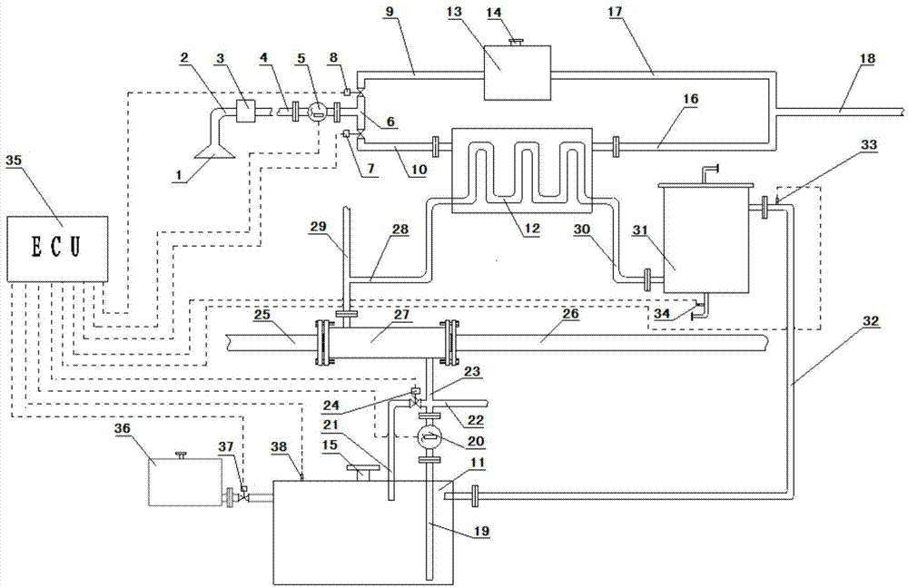
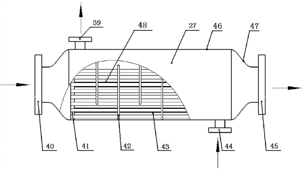
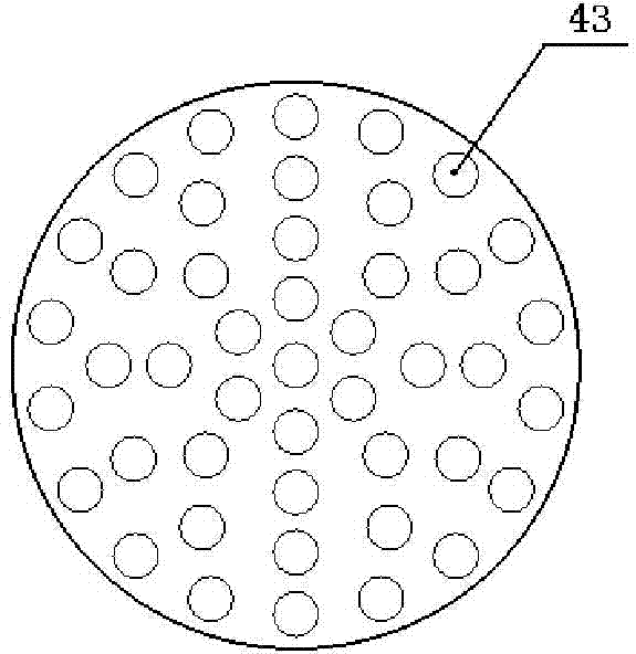
[0021] combine Figures 1 to 5 , LNG heating system for marine gas / dual fuel engine based on exhaust energy recovery, including: liquid collecting pan 1, liquid filter 3, adjustable flow pumps 5 and 20, remote control shut-off valves 24 and 37, heat exchange medium tank 11, Radiator 12, automatic replenishment tank 36, liquid level sensor 38, engine expansion tank 13, remote control butterfly valves 7 and 8, exhaust heat exchanger 27, LNG vaporizer 31, pipelines 2, 4, 6 and 9, etc. Lan and control system 35. The LNG system consists of two cycles: closed cycle and open cycle. The closed cycle is composed of heat exchange medium tank 11, adjustable flow pump 20, exhaust heat exchanger 27, LNG vaporizer 31, pipelines 19, 23, 28, 30, 32 and flanges. The adjustable flow pump 20 pumps the heat exchange medium through the pipeline 19 inserted into the bottom of the ...


PUM


Abstract

The invention aims at providing a ship gas / dual fuel engine LNG gasifying system based on exhaust energy recycling and a control method thereof. The ship gas / dual fuel engine LNG gasifying system comprises a heat transfer medium box, an exhaust heat exchanger, a heat dissipating device, an engine expansion water tank, an LNG gasifier and a liquid collecting plate. A heat transfer medium in the heat transfer medium box enters the exhaust heat exchanger through a first adjustable flow pump, enters the LNG gasifier after flowing through the heat dissipating device and then flows back to the heat transfer medium box, an external water source enters the engine expansion water tank and the heat dissipating device respectively through the liquid collecting plate and a three-way valve and then is drained, the external water source entering the heat dissipating device and the heat transfer medium are not mixed, and in other words, the external water source and the heat transfer medium flow in corresponding pipelines. The ship gas / dual fuel engine LNG gasifying system is high in heat dissipating capability and good in LNG gasifying effect, the engine exhaust emission heat can be recycled fully, the fuel utilization efficiency of an engine is improved, and the working environment of cabin marine engine operators can be obviously improved.

Description

technical field [0001] The invention relates to an engine attachment device and a control method, in particular to a marine engine attachment device and a control method. Background technique [0002] With the increasingly prominent problems of energy shortage and environmental pollution, the implementation of energy diversification strategies and the development of new energy technologies have become an inevitable trend in future development. Among all alternative energy sources, natural gas is the most abundant primary energy source, and it burns very cleanly. It is an alternative to petroleum. the most ideal solution. [0003] LNG is the liquid form of natural gas. When the gaseous natural gas is cooled to -162°C under normal pressure, it will condense into a liquid. The volume of natural gas after liquefaction is about 1 / 625 of the volume of the same amount of gaseous natural gas, which can greatly save storage and transportation space. LNG is basically used on ships. ...

Claims


Application Information

Patent Timeline
Patent Type & Authority Applications(China)
IPC IPC(8): F02M21/06F02G5/02
CPCY02T10/166Y02T10/32Y02T10/12Y02T10/30
Inventor 杨立平宋恩哲石兴超马修真姚崇杨晓涛丁顺良
Owner HARBIN ENG UNIV
Why Eureka
Try Eureka