Molecular imprinting microfluidics sensor based on double-annular-fiber-core optical fiber and double-annular-fiber-core optical fiber

A molecular imprinting and microfluidic technology, applied in multi-layer core/clad optical fibers, clad optical fibers, instruments, etc., can solve the problems of poor interferometer structure selectivity, complex system structure, large volume, etc., and achieve a simple structure. , compact structure, high detection sensitivity effect

Inactive Publication Date: 2014-07-02
HARBIN ENG UNIV
View PDF5 Cites 7 Cited by
  • Summary
  • Abstract
  • Description
  • Claims
  • Application Information

AI Technical Summary

Problems solved by technology

The Michelson-type fiber optic interferometer composed of this special fiber has two disadvantages: (1) As long as the refractive index outside the interference arm changes, it can cause changes in the interference signal
However, there are many factors that cause the refractive index of the medium to be measured to change, so the selectivity of this interferometer structure is poor; (2) Since the interference arm is located on the outer surface of the optical fiber, the sample cell must be designed for the sensor, so the system occupies a large volume, and the system structure is relatively complex

Method used


Image

  • Molecular imprinting microfluidics sensor based on double-annular-fiber-core optical fiber and double-annular-fiber-core optical fiber
  • Molecular imprinting microfluidics sensor based on double-annular-fiber-core optical fiber and double-annular-fiber-core optical fiber
  • Molecular imprinting microfluidics sensor based on double-annular-fiber-core optical fiber and double-annular-fiber-core optical fiber

Examples


Embodiment Construction

[0024] The present invention will be described in more detail below with examples in conjunction with the accompanying drawings.

[0025] The molecularly imprinted optical fiber online sensor based on the Mach-Zehnder type optical fiber interferometer of the present invention is realized in this way: an optical fiber containing a double annular core is used to connect the interference optical path and perform sensing, and its features mainly include the following:

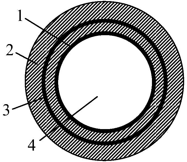
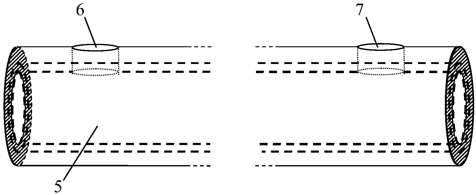
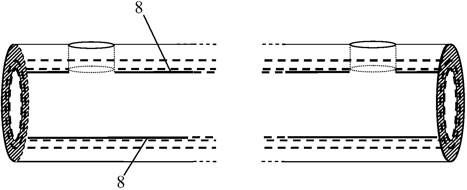
[0026] combine figure 1 , The main feature of the structure of the end face of the double-ring core optical fiber for sensing is that it has a double-ring core and a channel structure, and the core has a large specific surface area. The fiber core [1] is located on the inner surface of the annular cladding [2], and the fiber core [3] is located inside the annular cladding [2]. Such as figure 2 As shown, the surface of the microfluidic channel[4] utilizes CO 2 The laser opens two microports, in which the micropo...


PUM

PropertyMeasurementUnit
diameteraaaaaaaaaa
thicknessaaaaaaaaaa
diameteraaaaaaaaaa

Abstract

The invention provides a molecular imprinting microfluidics sensor based on a double-annular-fiber-core optical fiber and the double-annular-fiber-core optical fiber. The double-annular-fiber-core optical fiber comprises two annular fiber cores and a microfluid channel [4], wherein the first annular fiber core [1] is positioned on the inner wall of an annular wrapping layer [2]; the second fiber core [3] is positioned inside the annular wrapping layer [2]; the microfluid channel [4] is used as a sample sensing field; a molecular imprinting sensitive layer [8] is arranged on the inner surface of the annular fiber core [1]; micro holes [6] and [7] are formed in the surface of the double-annular-fiber-core optical fiber; two micro holes are positioned in one same side of the double-annular-fiber-core optical fiber; the double-annular-fiber-core optical fiber [5] is connected with an incident optical fiber [11] and an emergent optical fiber [12] through optical fiber pull conical points [9] and [10]; the incident optical fiber [11] is connected with an optical fiber coupler [16]; the optical fiber coupler [16] is connected with a light source [17]; the emergent optical fiber [12] is connected with a spectrometer [18]. The sensor is simple in structure and small in size, and can achieve high-selectivity on-line microfluidics detection.

Description

technical field [0001] The invention relates to a microfluidic molecular imprinting sensing device in an optical fiber, in particular to a high-sensitivity microfluidic on-line sensor based on an optical fiber containing a double-ring core and a trace amount of liquid molecular imprinting. Background technique [0002] Optical fiber sensor is one of the hot areas of scientific research today, and has extremely broad application prospects in the fields of biology, environment, and chemistry. Optical fiber sensors are divided into intensity absorption type, fluorescent type, and phase modulation type. Among them, the optical fiber sensor based on the principle of interference is realized based on phase modulation. The refractive index of the medium outside the arm changes, and then changes the phase of the two beams of light, resulting in a change in the interference spectrum, thereby detecting the physical quantity to be measured. The integrated optical fiber interferometer ...

Claims


Application Information

Patent Timeline
Patent Type & Authority Applications(China)
IPC IPC(8): G01N21/45G01N33/544G02B6/036
Inventor 杨兴华苑婷婷李恩涛刘春兰赵恩铭苑立波
Owner HARBIN ENG UNIV
Why Eureka
Try Eureka