Quantum well luminescent layer and formation method thereof

A light-emitting layer, quantum well technology, applied in semiconductor devices, electrical components, circuits, etc., can solve the problems of difficult to obtain crystal quality, low internal quantum efficiency, low compound luminous efficiency, etc., to reduce the Stark effect, weaken the internal Electric field, reducing the effect of non-radiative luminescence

Inactive Publication Date: 2014-07-09
BYD CO LTD
View PDF2 Cites 21 Cited by
  • Summary
  • Abstract
  • Description
  • Claims
  • Application Information

AI Technical Summary

Problems solved by technology

The disadvantages of this existing technology are: (1) Due to the low decomposition temperature of InN, the growth temperature of InN is low, it is difficult to obtain good crystal quality, and the increase of defects, dislocations, or non-radiative recombination centers leads to low internal quantum efficiency; ( 2) The strong self-built electric field in the quantum well forces the energy band to tilt, causing the electrons and holes to be separated in space, and the wave functions of the electrons and holes overlap and shift, resulting in the recombination of electrons and holes in the quantum well. (3) The lattice mismatch between GaN and InN is easy to introduce dislocation defects and form non-radiative recombination centers, resulting in low internal quantum efficiency

Method used

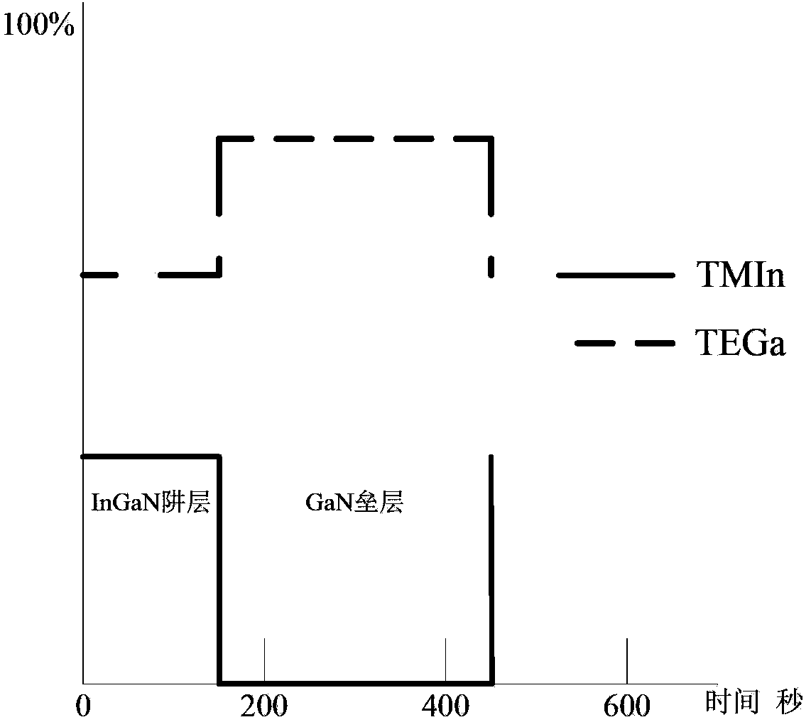
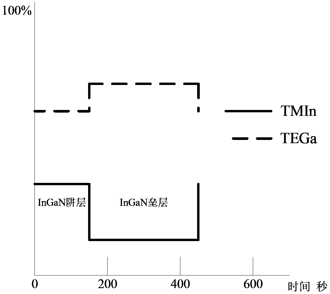

Image

  • Quantum well luminescent layer and formation method thereof
  • Quantum well luminescent layer and formation method thereof
  • Quantum well luminescent layer and formation method thereof

Examples


Embodiment Construction

[0024] Embodiments of the present invention are described in detail below, examples of which are shown in the drawings, wherein the same or similar reference numerals designate the same or similar elements or elements having the same or similar functions throughout. The embodiments described below by referring to the figures are exemplary and are intended to explain the present invention and should not be construed as limiting the present invention.

[0025] In describing the present invention, it should be understood that the terms "center", "longitudinal", "transverse", "length", "width", "thickness", "upper", "lower", "front", " Orientation or position indicated by "back", "left", "right", "vertical", "horizontal", "top", "bottom", "inner", "outer", "clockwise", "counterclockwise", etc. The relationship is based on the orientation or positional relationship shown in the drawings, and is only for the convenience of describing the present invention and simplifying the descrip...


PUM


Abstract

The invention brings forward a quantum well luminescent layer and a formation method thereof. The method comprises the following steps: forming an InGaN trap layer; and forming an InGaN barrier layer on the InGaN trap layer. The formation of the InGaN barrier layer further comprises forming an InGaN heating layer on the InGaN trap layer, forming an InGaN stabilizing layer on the InGaN heating layer, and forming an InGaN cooling layer on the InGaN stabilizing layer, wherein the indium content in the InGaN trap layer is first indium content, the indium content in the InGaN barrier layer is second indium content, and the first indium content is greater than the second indium content. By using the quantum well luminescent layer and the formation method thereof, the internal quantum efficiency of the quantum well luminescent layer can be improved, the LED epitaxial wafer luminescence efficiency is improved, and the quantum well luminescent layer and the formation method thereof are more suitable for the demand of a large-power epitaxial wafer.

Description

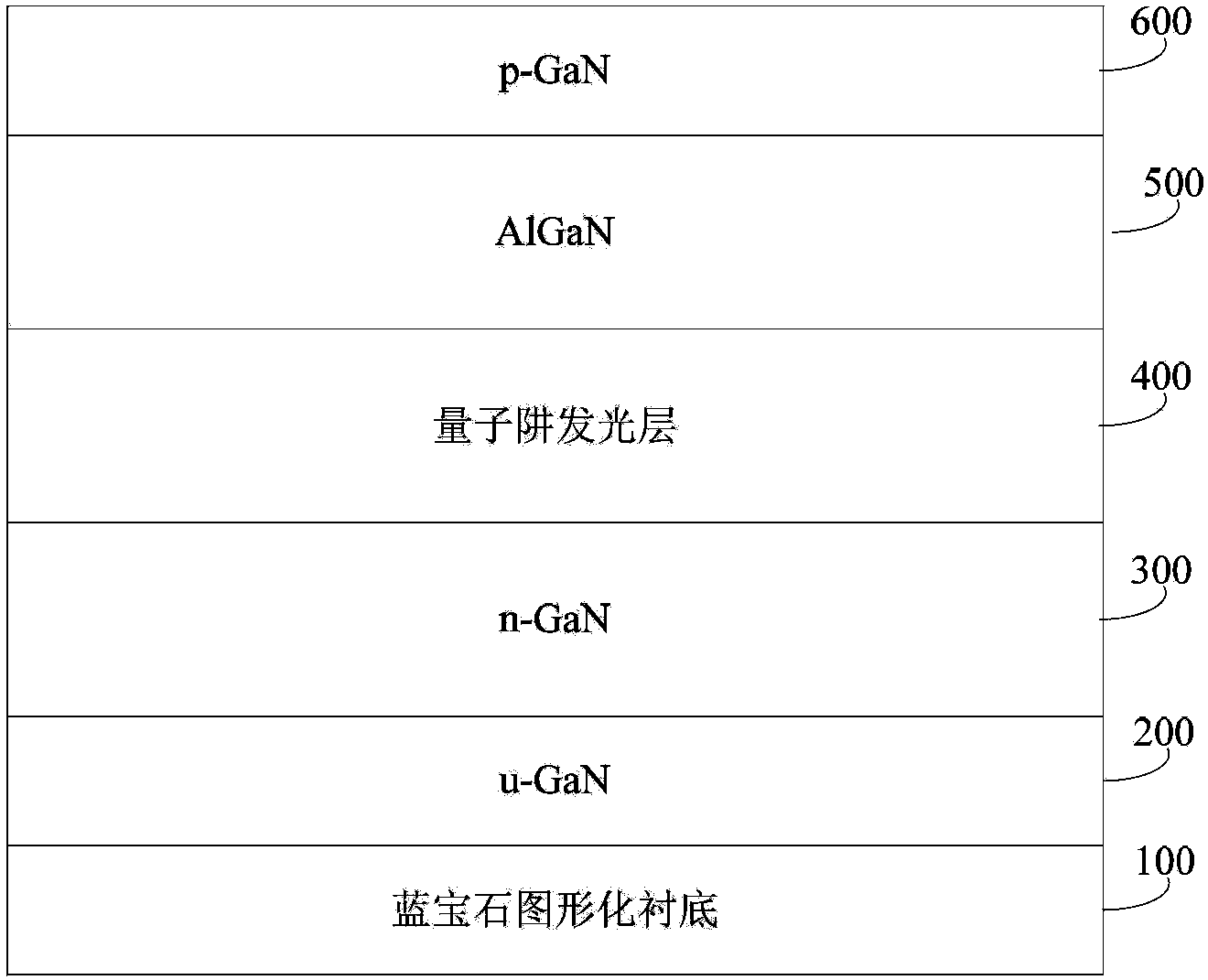
technical field [0001] The invention relates to the technical field of semiconductors, in particular to a quantum well light-emitting layer and a forming method thereof. Background technique [0002] With the development of LED indoor lighting and the demand for manufacturing high-power chips, the growth of quantum well light-emitting layers with good performance has become the focus of research in the field of semiconductor lighting. Most of the existing LED chip structures are based on GaN, and its structure is as follows: figure 1 As shown, from bottom to top, it includes: sapphire patterned substrate 100, undoped intrinsic gallium nitride layer (u-GaN) 200, N-type doped gallium nitride layer (n-GaN) 300, quantum Well light-emitting layer 400 , aluminum gallium nitride layer (AlGaN) 500 for current blocking, and P-type doped gallium nitride layer (p-GaN) 600 . Among them, the quantum well light-emitting layer 400 is the core part. [0003] Since the three and five grou...

Claims


Application Information

Patent Timeline
Patent Type & Authority Applications(China)
IPC IPC(8): H01L33/06H01L33/00
CPCH01L33/0075H01L33/06H01L33/325
Inventor 吴明驰
Owner BYD CO LTD
Why Eureka
Try Eureka