Vapor-phase deposition preparation method of load type iron catalyst
An iron catalyst, vapor deposition technology, applied in catalyst activation/preparation, molecular sieve catalysts, chemical instruments and methods, etc., can solve the problems of high safety cost, strong toxicity and explosive capacity, etc. Strong control effect
- Summary
- Abstract
- Description
- Claims
- Application Information
AI Technical Summary
Problems solved by technology
Method used
Image

Examples
preparation example Construction
[0026] The preparation method of the supported iron catalyst comprises the following steps.
[0027] Step 1, filling of the catalyst carrier; the specific method is as follows:
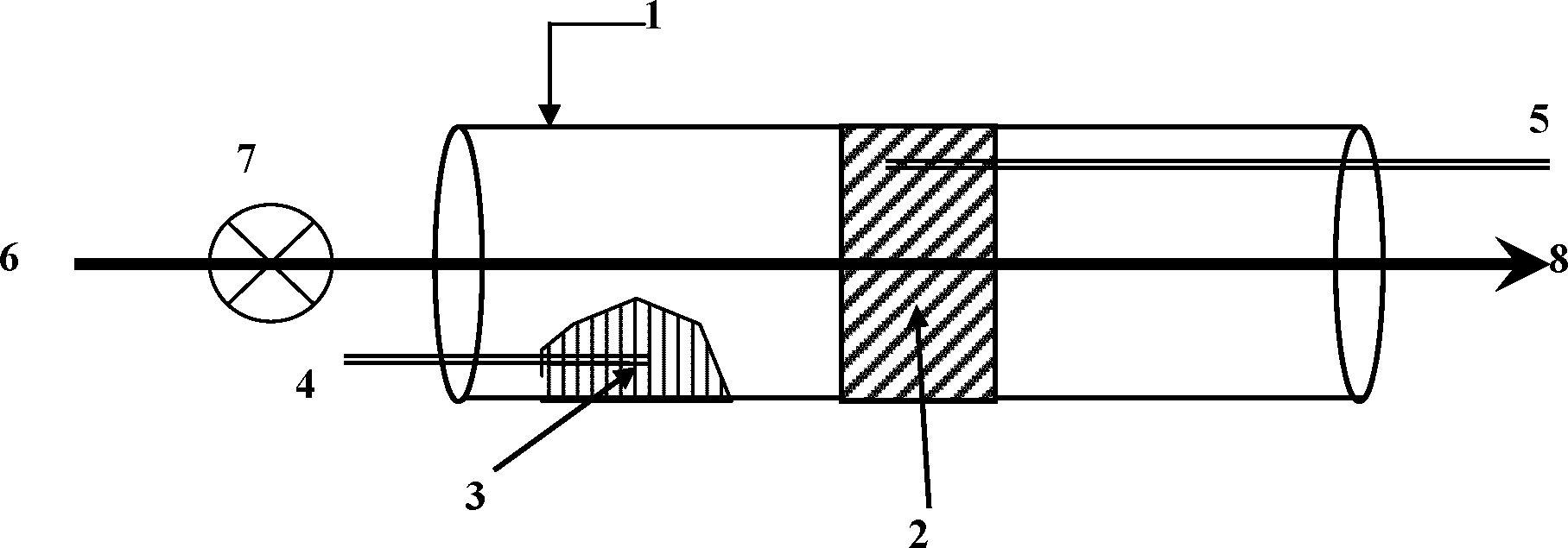
[0028] The catalyst carrier is Al 2 o 3 , SiO 2 , aluminosilicate, zeolite molecular sieve, MgO or ZrO 2 One or a mixture of several of them; the catalyst carrier is granular, and the particle size is within the range of 10 to 100 mesh; the catalyst carrier is filled in the reaction tube, and the catalyst carrier fills the cross section of the reaction tube to form a catalyst carrier bed 3; The catalyst carrier bed 3 is fixed by metal mesh, glass wool or quartz wool.
[0029] Step 2, place the ferrocene heap; the specific method is as follows:
[0030] A ferrocene stack is placed near the inlet end in the reaction tube; the mass ratio of the ferrocene to the catalyst carrier is 1:30 to 20:1; the center distance between the ferrocene stack and the catalyst carrier bed 3 is 0 to 50 cm;
[0031] St...
Embodiment 1
[0040] The preparation device of supported iron catalyst such as figure 1 As shown, the material of the reaction tube is quartz; the first thermocouple and the second thermocouple are K-type thermocouples; the stop valve and gas pipeline are made of stainless steel; the gas source is high-purity N 2 and compressed air; the flow rate of the source gas is controlled and displayed by a flow meter.
[0041] The preparation method of supported iron catalyst, the preparation steps are as follows:
[0042] Step (1), weigh 1.0 g γ-Al 2 o 3 Carrier, particle size is 20~50 mesh, according to figure 1 Place in a quartz reaction tube and fix it with wire mesh.
[0043] Step (2), take by weighing 0.8 g ferrocene solid, press figure 1 The way to put into the reaction tube, ferrocene pile and the center distance of the carrier layer is 10 cm.
[0044] Step (3), with N 2 As the air source, open the shut-off valve to make N 2 Into the inlet end of the reaction tube, N 2 The flow rate ...
Embodiment 2
[0048] Embodiment two, The difference with Example 1 is: step (1) uses γ-Al 2 o 3 The particle size of the carrier is 40-80 mesh. Step (3) The temperatures measured by the two thermocouples are both 130°C; N 2 The flow rate is 40 mL / min. Step (5) The second thermocouple shows a temperature of 400 o C; the time is 6h.
[0049] After the preparation, the iron content in the catalyst was analyzed to be 5.5 wt%, and the size of the nano-iron was analyzed by transmission electron microscope to be 2-7nm.
PUM
| Property | Measurement | Unit |
|---|---|---|
| Size | aaaaa | aaaaa |
| Size | aaaaa | aaaaa |
| Size | aaaaa | aaaaa |
Abstract
Description
Claims
Application Information
 - Generate Ideas
- Intellectual Property
- Life Sciences
- Materials
- Tech Scout
- Unparalleled Data Quality
- Higher Quality Content
- 60% Fewer Hallucinations
Browse by: Latest US Patents, China's latest patents, Technical Efficacy Thesaurus, Application Domain, Technology Topic, Popular Technical Reports.
© 2025 PatSnap. All rights reserved.Legal|Privacy policy|Modern Slavery Act Transparency Statement|Sitemap|About US| Contact US: help@patsnap.com