Method for generating vortex light with rotation angular momentum and vortex light array with rotation angular momentum

A technology of rotating angular momentum and vortex light, applied in optics, optical components, radiation/particle processing, etc., which can solve problems such as constraints, short particle manipulation distances, and difficult optical waveguide fabrication and optical coupling.

Inactive Publication Date: 2014-07-23
CENT SOUTH UNIV
View PDF6 Cites 13 Cited by
  • Summary
  • Abstract
  • Description
  • Claims
  • Application Information

AI Technical Summary

Problems solved by technology

However, the above methods all have problems such as short particle control distance and harsh conditions for forming the control beam.
Although the rotation phase or polarization characteristics of the beam can be used to rotate the particle in the observation plane perpendicular to the beam propagation direction, such as the vortex beam[4] and the circularly polarized beam[5], but this type of beam can only rotate the particle and cannot Particles move in a straight line on the viewing plane
Although it is possible to move particles along the waveguide by using an optical waveguide placed on the observation plane [6], the fabrication and optical coupling of the optical waveguide are still very difficult problems
Since the cross-sectional size of the optical waveguide is at the micron or submicron level, and the selection of materials needs to consider the refractive index of the solution instead of the refractive index of air, on the other hand, the efficient and convenient optical coupling between the light beam of the external light source and the optical waveguide is still It is one of the current technical bottlenecks, therefore, the application of optical waveguides for optical tweezers is still restricted

Method used


Image

  • Method for generating vortex light with rotation angular momentum and vortex light array with rotation angular momentum
  • Method for generating vortex light with rotation angular momentum and vortex light array with rotation angular momentum
  • Method for generating vortex light with rotation angular momentum and vortex light array with rotation angular momentum

Examples


Embodiment 1

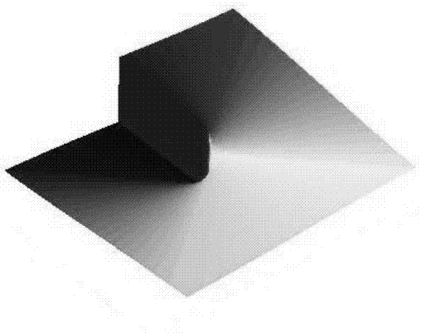
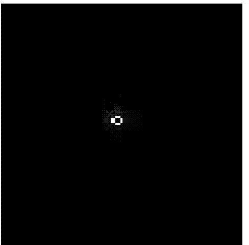
[0071] Example 1: The method of generating one vortex light:

[0072] see Figure 7-8 , and a description in the Summary section.

[0073] A method for generating vortex rays with rotational angular momentum, irradiating a collimated light beam with a phase plate with a rotational phase distribution, and forming an image on an imaging plane perpendicular to the optical axis; it is characterized in that the azimuth angle of the phase plate It is: 【The azimuth is also called the Azimuth angle, which is the horizontal angle between the north-pointing direction line of a certain point and the target direction line in a clockwise direction. 】

[0074] θ=a y / x;

[0075] In the formula, x and y are the coordinate point values ​​in the x and y axis directions respectively, a is the azimuth proportional constant, which is a real constant; and a≠1; [when a is 1, the imaging is circular, and the absolute value of a The farther the value is from 1, the closer the image is to a straigh...

Embodiment 2

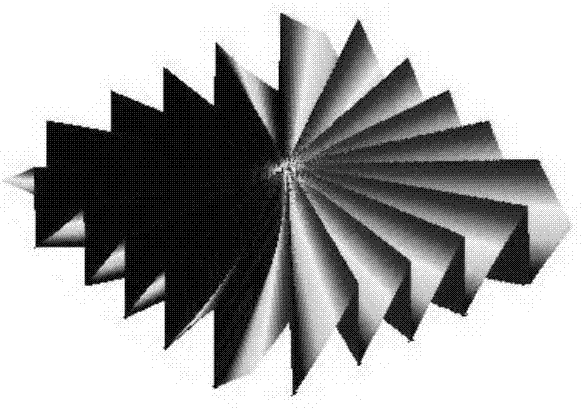
[0080] Embodiment 2: the method for producing vortex light array

[0081] see Figure 9-10 , and a description in the Summary section.

[0082] A method for generating a vortex light array with rotational angular momentum, superimposing N-1 phase images on the phase sheet of Embodiment 1 to form a phase sheet with a new rotation phase distribution, N is an integer, and N≥2;

[0083] The superposition is to add the phase value corresponding to each phase map with the phase value corresponding to another phase map directly according to the method of formula (1). The corresponding phase is 2pi*100 / 256, and the gray value of the m rows and n columns of the B phase map is 150, so the corresponding phase is 2pi*150 / 256, and the m rows and n columns of the superimposed phase map The phase is 2pi*150 / 256, which is converted into a gray value, and the same operation is performed on all points in turn to obtain the corresponding phase gray image after superimposition.

[0084] Irradi...


PUM


Abstract

The invention discloses a method for generating vortex light with rotation angular momentum and a vortex light array with rotation angular momentum. On the basis of the shaping principle that a phase plate with rotation phase distribution is irradiated by a collimated light beam to generate a vortex light beam, the azimuth angle of a rotation phase and a proportional constant are multiplied, the rotation order of the rotation phase is in an ultrahigh level, and therefore the light which is similar to a line in light intensity distribution is generated in the observation (or imaging) plane perpendicular to the optical axis direction. Because the light is generated by the rotation phase and has rotation angular momentum, the light is called as the vortex light. The light beam can move particles on the observation plane perpendicular to the optical axis direction in a non-mechanical-moving mode. Multiple rotation phases modulated by blazed gratings are overlapped and distributed on the same phase plate, so that vortex light arrays arrayed in parallel are generated. The generated light beam has a unique optical characteristic, the generating method is simple and flexible, and the method can be used for the fields of optical tweezers technologies, light beam shaping and laser application.

Description

technical field [0001] The invention belongs to the fields of beam shaping, beam application and optical tweezers technology. The method of beam shaping is used to generate vortex light or vortex light array, which can be used for laser to move particles on the imaging plane without mechanical manipulation, laser processing, or new beam property analysis. etc., the present invention specifically relates to a method of generating vortex rays and arrays of vortex rays with rotational angular momentum. Background technique [0002] In recent years, with the development of beam shaping technology and micro-nano technology, optical tweezers technology has received extensive attention and practical applications in many fields such as physics, electronics, chemistry, materials, metallurgy, medicine, and biology. Optical tweezers technology is a technology that uses highly focused laser beams to fix, move, stretch, or rotate to manipulate tiny objects at the micron, nanometer, or ev...

Claims


Application Information

Patent Timeline
Patent Type & Authority Applications(China)
IPC IPC(8): G02B27/09G21K1/00
Inventor 陶少华
Owner CENT SOUTH UNIV
Why Eureka
Try Eureka