
Long-distance distributed type large-measuring-range rapid response optical fiber dynamic strain sensing device

A measurement range and fast response technology, applied in the direction of measuring devices, optical devices, instruments, etc., can solve the problems of sacrificing the signal-to-noise ratio of the sensing system, unfavorable dynamic strain high-speed demodulation, unstable working state of the system, etc., to achieve expansion Dynamic strain measurement range, the effect of realizing quantitative real-time online high-speed measurement

Active Publication Date: 2014-07-30
SOUTH CHINA UNIV OF TECH
View PDF6 Cites 25 Cited by
  • Summary
  • Abstract
  • Description
  • Claims
  • Application Information

AI Technical Summary

Problems solved by technology

In 2009, A.Minardo et al. proposed a scheme for frequency offset hypotenuse offset detection (see R.Bernini, et al., Opt.Lett.34, 2613(2009) for details), realizing the Brillouin gain The drift of the spectrum is converted into the fluctuation of the detection optical power, thus greatly improving the system response speed to 98Hz, but the dynamic strain measurement range of this scheme is less than ±350με (deformation range ±0.035%)
In 2011, A.Voskoboinik et al. proposed a scheme for reconstructing the Brillouin gain spectrum without scanning (see A.Voskoboinik, et al., US Patent, US20130025374A1, (2013) for details), which can cover without scanning Sensing spectrum, so the response speed can also reach the order of tens of Hz, but the dynamic strain measurement range of this technical solution can only reach ±900με
In 2011, on the basis of the aforementioned frequency difference hypotenuse bias detection scheme, Q.Cui et al. used pulsed light with a pulse width of 6.5 ns as the pump pulse, which broadened the spectrum width of the Brillouin gain spectrum to 160 MHz, thereby realizing the The strain measurement range is extended to ±1600με (see Q.Cui, et al., IEEE Photon.Technol.Lett.23, 1887(2011) for details), but this technical solution sacrifices system response speed and signal-to-noise ratio
In 2012, Y.Peled et al. used an arbitrary waveform generator to drive an electro-optic modulator to achieve high-speed reconstruction of the distribution of the Brillouin gain spectrum (see Y.Peled, et al., Opt.Express20, 8584 (2012) ), but it takes time to extract strain-related Brillouin frequency shift information during signal processing, so this scheme sacrifices the response speed of the system when obtaining a larger strain sensing range, which is not conducive to high-speed demodulation of dynamic strain
Although these technical solutions can effectively expand the measurement range of dynamic strain to about ±2000με, they sacrifice the signal-to-noise ratio of the sensing system, so that the response speed can only reach about 10Hz, which cannot meet the demand for high response speed (100Hz) in practical applications.
[0007] All the above-mentioned distributed optical fiber dynamic strain measurement technology solutions, including fiber Bragg grating type, interference structure type and Rayleigh scattering type, all have shortcomings such as difficulty in building a large sensor network, unstable working state of the system, or difficulty in quantitative measurement. Meet the needs of practical applications
In the most potential dynamic strain sensing scheme based on the Brillouin effect, a technology that can take into account both large measurement range and high response speed has not been invented.

Method used


Image

  • Long-distance distributed type large-measuring-range rapid response optical fiber dynamic strain sensing device
  • Long-distance distributed type large-measuring-range rapid response optical fiber dynamic strain sensing device
  • Long-distance distributed type large-measuring-range rapid response optical fiber dynamic strain sensing device

Examples


Embodiment Construction

[0034] The implementation of the present invention will be further described below in conjunction with the examples and drawings, but the implementation and protection of the present invention are not limited thereto.

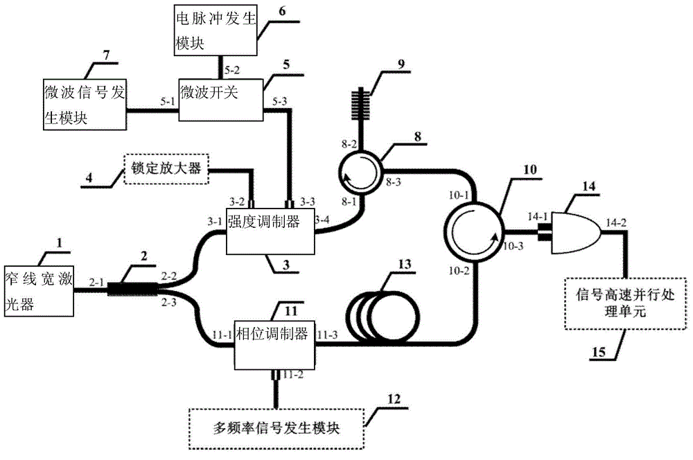
[0035] The structural design of the long-distance distributed large-scale measurement range fast-response optical fiber dynamic strain sensing device is as follows: image 3 As shown, the pigtail output of the narrow linewidth laser 1 is connected to the input port 2-1 of the fiber coupler 2, and the seed laser is divided into two paths, one of which passes through the output port 2-2 of the fiber coupler 2 and the intensity modulator 3 The input port 3-1 of the intensity modulator 3 is connected, and the DC voltage bias port 3-2 of the intensity modulator 3 is connected with the lock-in amplifier 4, so as to realize the automatic feedback stabilization control of the optimal operating point of the intensity modulator 3; the radio frequency input port of the int...


PUM

PropertyMeasurementUnit
Line widthaaaaaaaaaa

Abstract

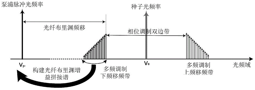
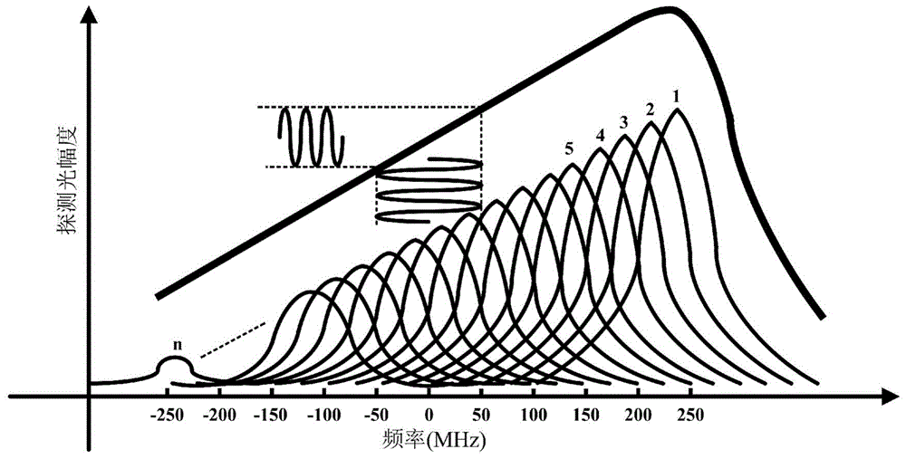
The invention provides a long-distance distributed type large-measuring-range rapid response optical fiber dynamic strain sensing device. The device comprises a phase modulator, a multi-frequency signal generating module, an intensity modulator, a microwave switch, an electric pulse generating module, a microwave signal generating module and other components. The signal generating module comprising multi-frequency components is used for modulating the phase of detection continuous light, so that multi-light-frequency components are generated in the detection continuous light, and corresponding Brillouin gain spectrum amplitudes are adjusted through controlling the amplitudes of all the light-frequency components in the detection continuous light. A Brillouin gain spectrum of a needed spectrum width and a spectrum type is obtained through splicing, and the dynamic strain measuring range is greatly enlarged under the condition that the signal-to-noise ratio and the response speed of a system are not destroyed. The frequency difference between two light beams generating a Brillouin amplification effect is fixed in the middle of a beveled edge linear region of the spliced Brillouin gain spectrum, drifting of the spliced Brillouin gain spectrum is converted into power fluctuation of the detection light, and long-distance distributed type large-measuring-range high response speed quantitative measuring on optical fiber dynamic strain and optical fiber static strain is achieved.

Description

technical field [0001] The invention relates to the technical field of distributed optical fiber dynamic strain measurement, in particular to a long-distance distributed large measurement range fast response optical fiber dynamic strain sensing device. Background technique [0002] There are more and more damages to equipment and buildings caused by dynamic strain, especially in earthquake-prone areas, where vibration and shock waves can seriously damage dams, bridges and houses, etc., so there is an urgent need for dynamic strain sensing with fast response The internet. Because optical fiber has significant advantages such as low loss, high temperature resistance, corrosion resistance, insulation, and anti-electromagnetic interference, and has little impact on the health, safety, stability, and integrity of the research structure, fiber optic sensing technology has essentially become a building block. The best choice for distributed dynamic strain monitoring. [0003] At ...

Claims


Application Information

Patent Timeline
IPC IPC(8): G01B11/16
Inventor 甘久林陈佳利杨中民
Owner SOUTH CHINA UNIV OF TECH
Learn More