
Solar cell graphite boat and film coating method thereof

A technology of solar cells and graphite boats is applied in the field of building materials to achieve the effect of reducing the generation of chromatic aberration films, improving the uniformity of the coating and reducing the chromatic aberration

Inactive Publication Date: 2014-08-20
ALTUSVIA ENERGY TAICANG
View PDF5 Cites 10 Cited by
  • Summary
  • Abstract
  • Description
  • Claims
  • Application Information

AI Technical Summary

Problems solved by technology

[0003] Purpose of the invention: Propose a solution by changing the structure of the graphite boat, and provide a solar cell graphite boat and its coating method, which improves the coating uniformity of the graphite boat and solves the problem of the outer boat of the existing graphite boat coating. The thickness of the leaf film is too thick, and the film thickness of the medial navicular leaf is too thin

Method used


Image

  • Solar cell graphite boat and film coating method thereof
  • Solar cell graphite boat and film coating method thereof
  • Solar cell graphite boat and film coating method thereof

Examples


Embodiment 1

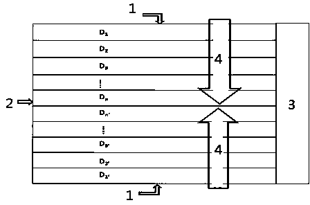
[0028] The distance between the blades of the conventional 19 graphite boats is 11mm. At this time, n=9, D1=D1'=D2=D2'=D3=D3'...=D9=D9'=11mm, and the voltage U applied between the blades At about 300V, the electric field intensity E between the boat blades is about 27.3kV / m, and the ability to excite plasma is the same. The diagram is attached figure 1 , denoted as graphite boat A.

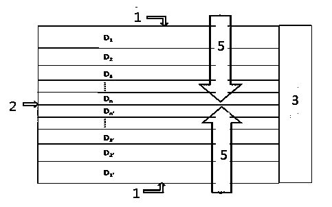
[0029] The embodiment of the present invention adopts the design of 19 graphite boats. At this time, n=9, and the distance between the boat blades from the outside of the graphite boat to the center is: D1=D1'=11.4mm, D2=D2'=11.3mm, D3=D3'= 11.2mm, D4=D4'=11.1mm, D5=D5'=11mm, D6=D6'=10.9mm, D7=D7'=10.8mm, D8=D8'=10.7mm, D9=D9'=10.6mm, At this time N=0.1mm. If the voltage U between the boat blades is kept constant at 300V, the electric field strength corresponding to the boat blade spacing is: E1=E1'=26.3kV / m, E2=E2'=26.5kV / m, E3=E3' =26.8kV / m, E4=E4'=27.0kV / m, E5=E5'=27.3kV / m, E6=E6'=27.5kV / m...

Embodiment 2

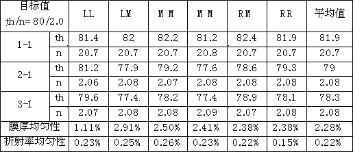
[0032] Use the same coating process to coat the graphite boat A and graphite boat B in Example 1 respectively. The single crystal silicon wafers used come from the same silicon ingot and are processed through the same conventional process: primary cleaning, diffusion and secondary Cleaning and film preparation go through the following steps: entering the boat, cleaning, purging, leak testing, pre-deposition, film deposition, purging, and exiting the boat. The process conditions of the pre-cleaning step are: temperature 450°C, nitrogen flow rate 2L / min, ammonia flow rate 6L / min, pressure 1.6Torr, radio frequency power 4.8kW, radio frequency switching time ratio Ton:Toff=4ms:48ms, duration 200s; the first pre-deposition process conditions are: temperature 450°C, nitrous oxide flow rate 6L / min, silane flow rate 0.8L / min, pressure 1.6Torr, duration 20s; the first layer thin film deposition process conditions are: temperature 450°C, nitrous oxide flow rate 6L / min, silane flow rate ...


PUM


Abstract

The invention discloses a solar cell graphite boat and a film coating method thereof. The solar cell graphite boat comprises two or more boat leaves. The boat leaf distance is of a tapered structure. The boat leaf distances are gradually reduced from the boat leaf on the outmost side to the boat leaf on the centremost position of the graphite boat, the boat leaf distances from one side of the boat leaf on the outmost side of the graphite boat to the boat leaf on the centremost position of the graphite boat are represented through D1, D2, D3...and Dn respectively, and the boat leaf distances from the other side of the boat leaf on the outmost side of the graphite boat to the boat leaf on the centremost position of the graphite boat are represented through D1', D2', D3'...and Dn' respectively, wherein Dn and Dn' are adjacent, D1=D1'>D2=D2'>D3=D3'...>Dn=Dn', and D1-D2=D2-D3=...=Dn-1-Dn=Dn. According to the solar cell graphite boat and the film coating method, the film coating evenness of the graphite boat is improved very well, and the problems that according to existing graphite boat coated films, the film of the boat leaf on the outer side is thick and the film of the boat leaf on the inner side is thin are solved.

Description

technical field [0001] The invention relates to the field of building materials, in particular to a solar cell graphite boat and a coating method thereof. Background technique [0002] At present, the photovoltaic market has higher and higher requirements for the appearance of crystalline silicon cells. Due to the problem of color difference, many high-efficiency cells cannot meet the appearance requirements of the market. The problem of color difference mainly refers to the color difference of each cell, which is mainly caused by the thickness of the silicon wafer film. . At this stage, both tubular PECVD and plate PECVD have the problem of coating color difference, and tubular PECVD is particularly serious, which has become one of the important factors affecting product yield. The chromatic aberration of tube coating is mainly related to the way of air intake and heating. At present, the gas inlet is distributed on the stainless steel ring near the furnace mouth, so comp...

Claims


Application Information

Patent Timeline
IPC IPC(8): H01L31/18H01L21/673H01L21/205
CPCC23C16/308C23C16/402C23C16/44H01L21/6732Y02P70/50
Inventor 张辉杨红冬刘仁中张斌邢国强
Owner ALTUSVIA ENERGY TAICANG
Features
  • Generate Ideas
  • Intellectual Property
  • Life Sciences
  • Materials
  • Tech Scout
  • Unparalleled Data Quality
  • Higher Quality Content
  • 60% Fewer Hallucinations
Learn More