

Water circulation structure of fuel gas corner tube hot-water boiler
A hot water boiler, water circulation technology, applied in the direction of fluid heaters, lighting and heating equipment, etc., can solve the problems of low temperature corrosion of flow heating surface tubes, stagnant water circulation, low flow rate, etc., to achieve high-quality flow rate, reduce flow deviation, The effect of high working fluid flow rate
- Summary
- Abstract
- Description
- Claims
- Application Information
AI Technical Summary
Problems solved by technology
Method used
Image

Examples
Embodiment Construction
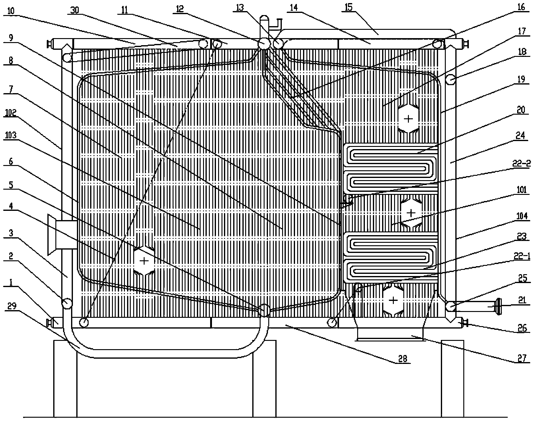
[0033] The present invention will be described in more detail below in conjunction with the accompanying drawings.
[0034] The gas angle tube hot water boiler water circulation structure of the present invention has a structure such as figure 1 As shown, it includes a furnace 103 and a convection shaft 101 arranged behind the furnace 103, a boiler front wall 102 is arranged in front of the furnace 103, a boiler rear wall 104 is arranged behind the convection shaft 101, and the top of the furnace 103 is arranged in sequence There are side wall III membrane type water cooling wall upper header 10, side wall II membrane type water cooling wall upper header 11, outlet header 12, side wall I membrane type water cooling wall upper header 14, and the bottom of the furnace 103 in sequence Set side wall III membrane type water cooling wall lower header 1, side wall II membrane type water cooling wall lower header 28, side wall I membrane type water cooling wall lower header 26, side w...
PUM
 Abstract
Description
Claims
Application Information