Method for manufacturing heat sink body

A manufacturing method and heat sink technology, applied in the direction of improving process efficiency and energy efficiency, can solve problems such as difficult to process structures and simplicity, and achieve the effects of increasing heat transfer efficiency, saving heat sink space, and improving heat dissipation performance

Active Publication Date: 2014-09-10
CHENGDU 3D CHANGE TECH
View PDF5 Cites 34 Cited by
  • Summary
  • Abstract
  • Description
  • Claims
  • Application Information

AI Technical Summary

Problems solved by technology

[0010] The purpose of the present invention is to address the defects of the above-mentioned heat sink production methods, and propose the present invention-a heat sink production method, which is different from the existing production technology forming principle, and can p

Method used


Image

  • Method for manufacturing heat sink body
  • Method for manufacturing heat sink body
  • Method for manufacturing heat sink body

Examples


Example Embodiment

[0040] Example one:

[0041] A 3D printing manufacturing method for heat sinks. The additive manufacturing equipment adopts EOSM270 and the supporting software is PSW3.5. The customer needs to prepare narrow channel heat sinks, and the material is chromium.

[0042] Step 1. Use proE, solidworks, UG, CATIA and other three-dimensional drawing software to design the overall three-dimensional shape of the heat sink, including the micro-channel structure inside the heat sink and the external positioning holes. The support cannot be removed after the internal channel is formed, so the design is appropriate The shape and size of the shaft avoid increasing the internal support that is difficult to remove;
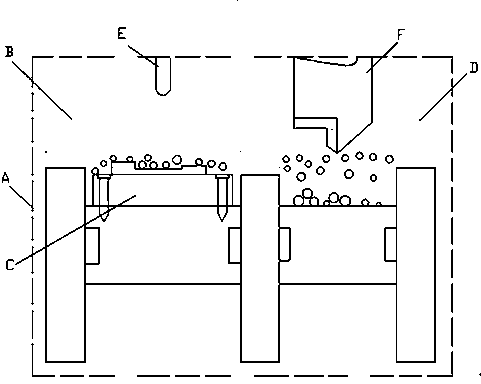
[0043] Step 2. Fill chromium powder into the powder tank of additive manufacturing equipment;

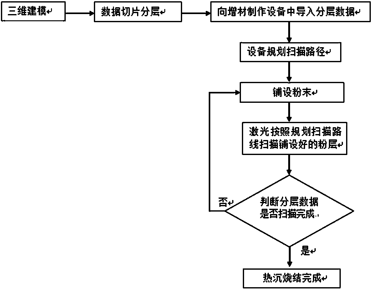
[0044] Step 3. Use the software RP-Tools to slice and layer the heat sink three-dimensional graphics: cut the heat sink three-dimensional graphics along the z-axis into a series of two-dimensio...

Example Embodiment

[0051] Embodiment two:

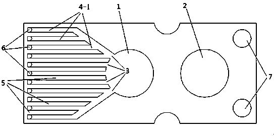
[0052] The manufacturing method of the structure of this example is a narrow channel heat sink integrally formed by additive manufacturing technology. The cooling water enters the water inlet channel 4 between the channel walls 5 through the water inlet hole 3 through the water inlet hole 3, the water inlet channel, and then The front end of the heat sink chip bonding enters the water outlet channel 9 through the water reflection hole 6, and finally enters the two wide water outlet channels through the water outlet channel hole 8 and enters the water outlet hole 2, thereby completing a cycle of cooling. The reason for the increase of the narrow water inlet and outlet channels and the longest possible channel wall is to maximize the heat exchange area, reduce the liquid movement speed, and improve the heat exchange efficiency. The channel height h3 at the water return hole 6 of the water outlet channel 9 is greater than the channel width h4 at the water ou...


PUM

PropertyMeasurementUnit
Thicknessaaaaaaaaaa
Oxygen contentaaaaaaaaaa

Abstract

The invention discloses a method for manufacturing a heat sink body. The method aims at solving the problems that in the traditional heat sink manufacturing process, heat resistance is increased due to multilayer welding, and a heat sink body needs to be manufactured through multiple processes and is short in service life. The method includes the steps that three-dimensional modeling is conducted on the whole structure of the heat sink body; a three-dimensional model is guided to a workbench computer, and the printing angle and positions are set according to the structure of a three-dimensional pattern; a powder layer laid on a base plate of a workbench in advance is sintered into two-dimensional shapes corresponding to the powder layer through high-energy laser beams according to the scanning path; powder as thick as the powder layer is laid on the workbench on which one layer of pattern is sintered, and lasers scan the powder according to the scanning path of the layer until the whole three-dimensional pattern is finished. Through the structure, the heat sink body has the advantages that pressure distribution is uniform and the service life of the heat sink body is prolonged.

Description

technical field [0001] The invention relates to a manufacturing method and structure of a microchannel cooling heat sink during heat dissipation and cooling of semiconductor lasers and array devices thereof, large-scale integrated circuits, etc., and belongs to the technical field of semiconductor electronic packaging. Background technique [0002] Microchannel Cooled Heatsink is a kind of Modular Microchannel Cooled Heatsinks (MCC for short). The advent of this effective low thermal resistance heat sink is closely related to the development of arrays, especially fully filled laser diode arrays for high duty cycle and even CW operation. MCC is produced by anisotropic chemical etching in silicon, and can be used as building blocks to overlap large two-dimensional structures according to the design needs of diode arrays. The low thermal resistance of MCC is dependent on the liquid refrigerant and its laminar flow through MCC. Its good thermal control performance is very suita...

Claims


Application Information

Patent Timeline
IPC IPC(8): B22F3/105
CPCY02P10/25
Inventor 王智勇闫岸茹李从洋张冬云
Owner CHENGDU 3D CHANGE TECH
Why Eureka
Try Eureka