Environmental-protection and energy-conversion type diaphragm electrolysis device
A diaphragm electrolysis and energy-saving technology, applied in the field of electrolysis, can solve the problems of high investment cost, affecting production capacity increase, high operating cost, etc., and achieve the effect of eliminating environmental pollution, reducing operating cost, and improving current efficiency
- Summary
- Abstract
- Description
- Claims
- Application Information
AI Technical Summary
Problems solved by technology
Method used
Image

Examples
Embodiment 1
[0019] Embodiment 1, taking electrolytic manganese as an example
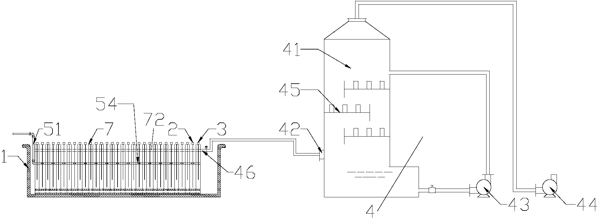
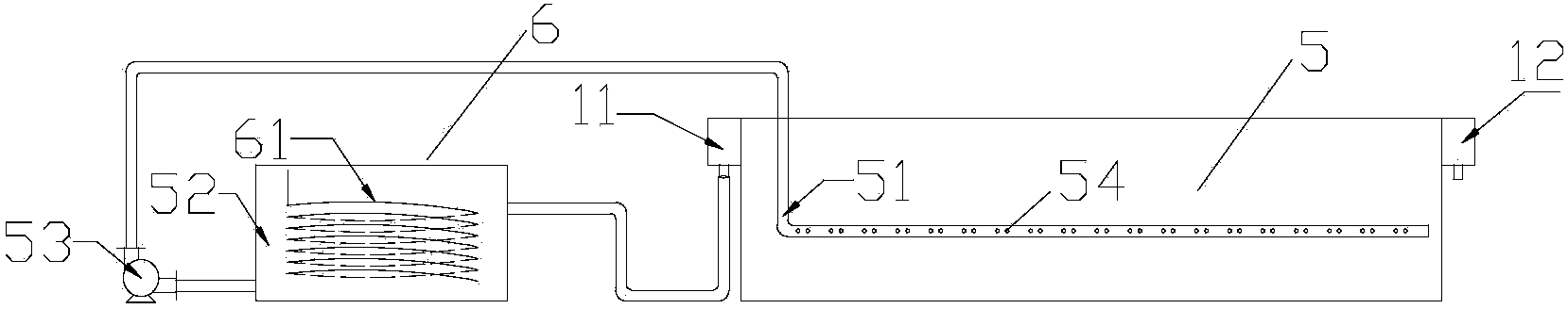
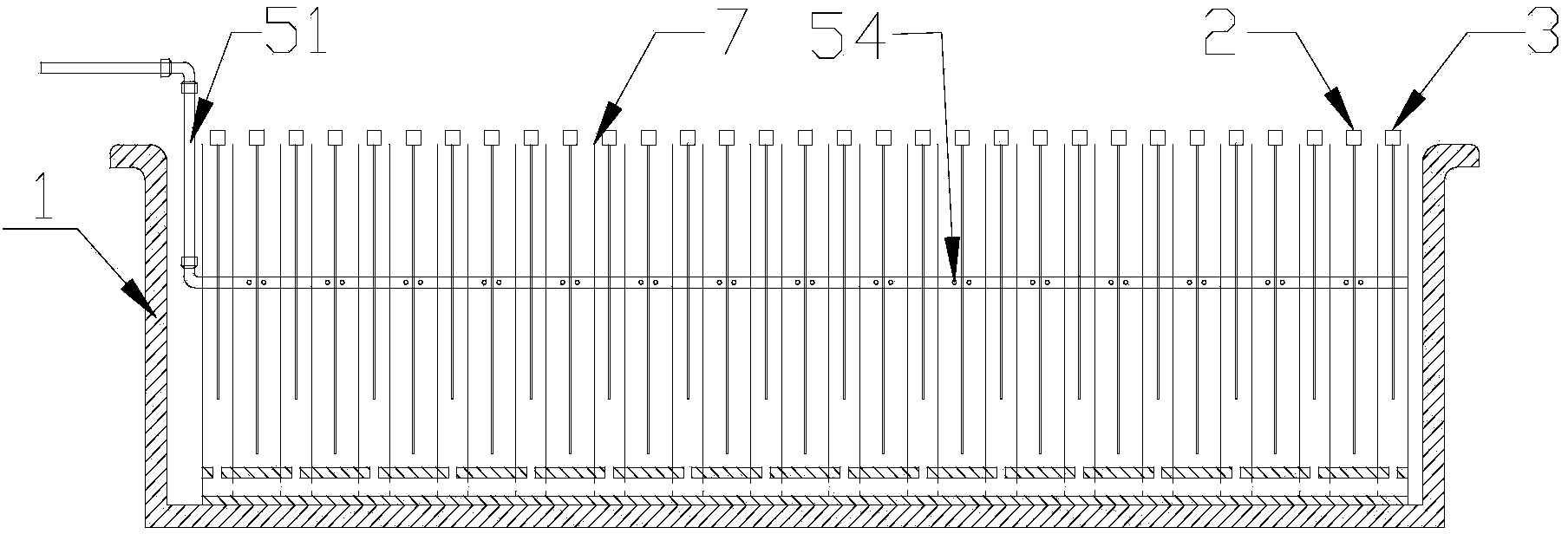
[0020] Adjust the pH of the manganese sulfate solution to 6.0-7.5, and control the temperature at 38-42°C. The manganese sulfate solution flows from the high-level launder to the electrolytic cell 1. After the manganese sulfate solution is filled with the electrolytic cell, the catholyte circulation pump 54 is turned on. The catholyte is self-circulated in the electrolytic cell, and a forced flow is formed on the surface of each cathode. When the catholyte circulation flow reaches 1500m 3 / Mt, increase the cathode current density to 350A / m 2 , After 1 day of electrolysis, the cathode product was taken out, and its cathode current efficiency reached 85%.
Embodiment 2
[0021] Embodiment 2 takes electrolytic manganese as an example
[0022] Adjust the pH of the manganese sulfate solution to 6.0-7.5, and control the temperature at 38-42°C. The manganese sulfate solution flows from the high-level launder to the electrolytic cell 1. After the manganese sulfate solution is filled with the electrolytic cell, the catholyte circulation pump 54 is turned on. The catholyte is self-circulated in the electrolytic cell, and a forced flow is formed on the surface of each cathode. When the catholyte circulation flow reaches 1000m 3 / Mt, increase the cathode current density to 350A / m 2 , After 1 day of electrolysis, the cathode product was taken out, and its cathode current efficiency reached 82%.
Embodiment 3
[0023] Embodiment 3 takes electrolytic manganese as an example
[0024] Adjust the pH of the manganese sulfate solution to 6.0-7.5, and control the temperature at 38-42°C. The manganese sulfate solution flows from the high-level launder to the electrolytic cell 1. After the manganese sulfate solution is filled with the electrolytic cell, the catholyte circulation pump 54 is turned on. The catholyte is self-circulated in the electrolytic cell, and a forced flow is formed on the surface of each cathode. When the catholyte circulation flow reaches 800m 3 / Mt, increase the cathode current density to 350A / m 2 , After 1 day of electrolysis, the cathode product was taken out, and its cathode current efficiency reached 80%.
PUM
 Abstract
Description
Claims
Application Information