Biodegradable composite material
A composite material and biological technology, applied in tissue regeneration, bone implants, medical science, etc., can solve the problems of inflammatory response, difficult to monitor the recovery process, difficult to distinguish bone grafts from healthy bone environment, etc.
- Summary
- Abstract
- Description
- Claims
- Application Information
AI Technical Summary
Problems solved by technology
Method used
Image
Examples
Embodiment 1
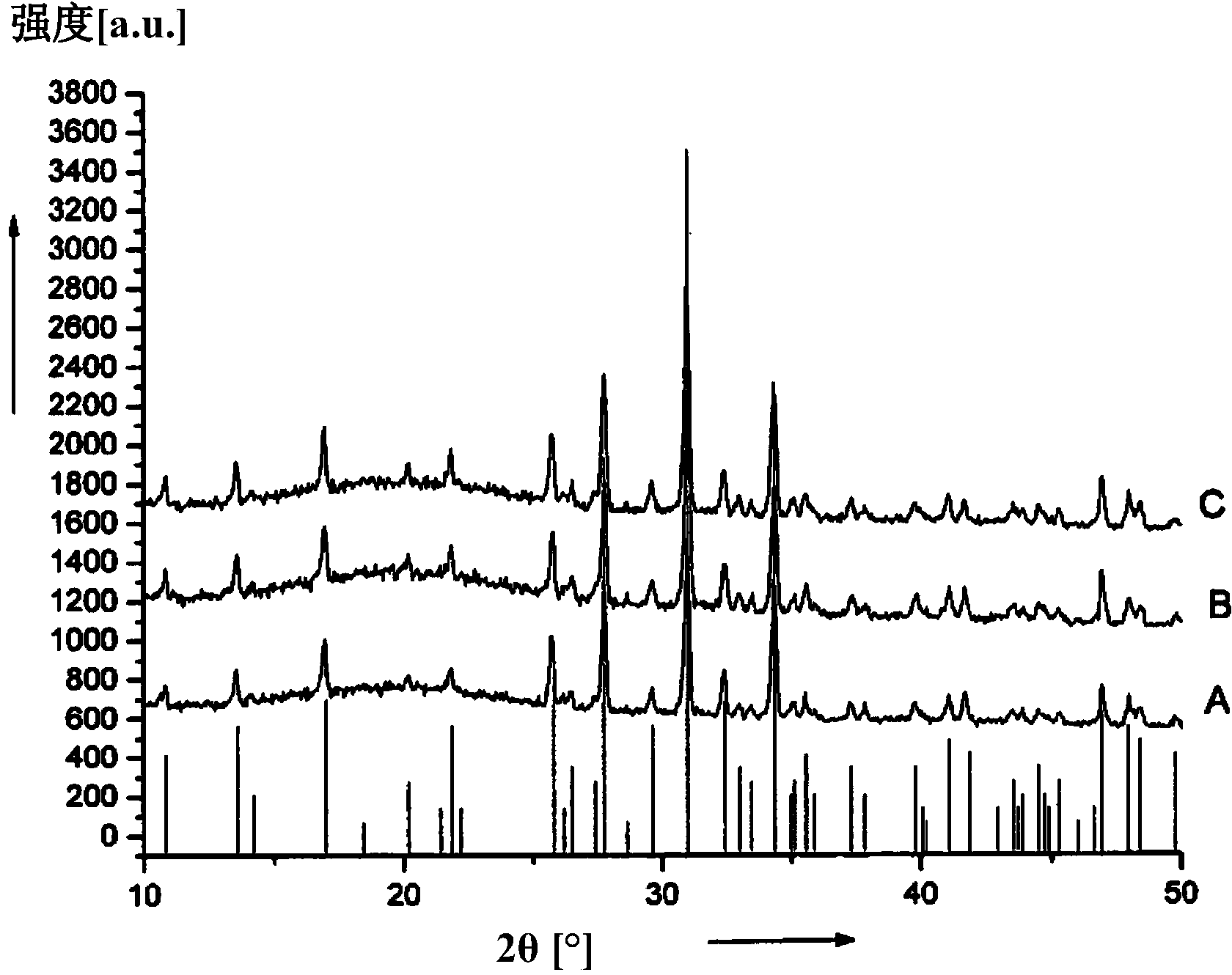
[0122] The 1000-2000 μm component I particle fraction was separated by sieving, and the 5.6 g portion was suspended in 20 ml of component D, and 74 μl of component P was added thereto. After 0, 1, 3, 6, and 23 hours, the material was filtered, washed, and dried. The particles were then washed, filtered and dried, and the particle size was tested using a laser dispersion device (Fritsch Analysette), the surface integrity was tested by scanning electron microscopy, and the phase purity was tested by X-ray powder diffraction. Table 1 shows the d of tricalcium phosphate powder after the action of acetic acid for different time 10 , D 50 And d 90 value.
[0123] Table 1
[0124]
[0125] It can be seen from Table 1 that there is a significant particle size reduction only after 6 hours. Use d for the fine powder fraction 10 The value indicates that it undergoes greater degradation than coarser fractions of particles fragmented. Correspondingly, it is believed that surface etching of sm...
Embodiment 2
[0128] 16.5 g of component O was added to 3.5 ml of component D and suspended by a colloid mill. The component I particle fraction of 1000-2000 μm was separated by sieving, and 5.6 g was added to the suspension. After adding 74 μl of component P, the material was stirred at room temperature. After 0, 30, 120, and 165 minutes, the acid was neutralized and the mixture was poured into a mold and freeze-dried. X-ray powder diffraction method was used to test whether the action time of acid has an effect on the phase stability of calcium phosphate. The results show that the effect of acid has no effect on the phase stability of the material.
Embodiment 3
[0130] A 150-500 μm particle fraction is separated from component H by sieving. The 150-500 μm fraction and the 1000-2000 μm fraction are separated from component I by sieving. According to Table 2, these components were mixed together in various ratios. 190 g of component O was suspended in 1000 ml of component D and ground by a colloid mill. 760 g of the granular mixture is added and the mixture is mixed intimately. After adding 10 ml of component B, the mixture was neutralized and poured into a square high-grade steel mold and freeze-dried. Depending on the freeze-drying process (slow or fast), composite materials with a density of 0.2 or 0.4 g / ml can be obtained. Table 2 provides information on the different mixtures and densities and the measured specific surface area.
[0131] Table 2: Measurement results of various collagen / ceramic composite materials compared with collagen
[0132]
[0133] It can be seen that 100% pure collagen has a surface area 5-8 times higher. Th...
PUM
| Property | Measurement | Unit |
|---|---|---|
| loose density | aaaaa | aaaaa |
| loose density | aaaaa | aaaaa |
| particle diameter | aaaaa | aaaaa |
Abstract
Description
Claims
Application Information
 - R&D
- Intellectual Property
- Life Sciences
- Materials
- Tech Scout
- Unparalleled Data Quality
- Higher Quality Content
- 60% Fewer Hallucinations
Browse by: Latest US Patents, China's latest patents, Technical Efficacy Thesaurus, Application Domain, Technology Topic, Popular Technical Reports.
© 2025 PatSnap. All rights reserved.Legal|Privacy policy|Modern Slavery Act Transparency Statement|Sitemap|About US| Contact US: help@patsnap.com


