Unlock instant, AI-driven research and patent intelligence for your innovation.
A method of sulfur-doping graphene
What is Al technical title?
Al technical title is built by PatSnap Al team. It summarizes the technical point description of the patent document.
A technology of graphene and sulfur doping, applied in the field of materials, to achieve the effects of controllable doping, simple and efficient sulfur doping, and low economic cost
Active Publication Date: 2016-12-28
SHANGHAI INST OF MICROSYSTEM & INFORMATION TECH CHINESE ACAD OF SCI
View PDF4 Cites 0 Cited by
Summary
Abstract
Description
Claims
Application Information
AI Technical Summary
This helps you quickly interpret patents by identifying the three key elements:
Problems solved by technology
Method used
Benefits of technology
Problems solved by technology
In graphene, electrons can move extremely efficiently, while traditional semiconductors and conductors, such as silicon and copper, do not perform as well as graphene
Method used
Image
Click on the blue label to locate the original text in one second.
Reading with bidirectional positioning of images and text.
Examples
Embodiment 1
[0035] Such as Figure 1 ~ Figure 3 As shown, this embodiment provides a method for sulfur doping graphene, which at least includes the following steps:
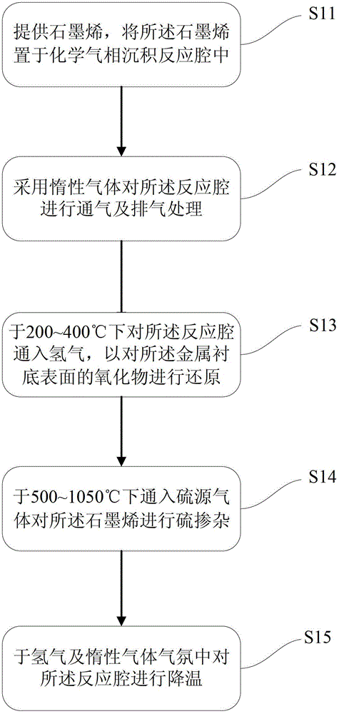
[0036] First, perform step 1) S11, provide graphene, and place the graphene in a chemical vapor deposition reaction chamber;
[0037] Then proceed to step 2) S12, using inert gas to vent and exhaust the reaction chamber;
[0038] Then proceed to step 3) S14, passing a sulfur source gas at 500 to 1050°C to sulfur dope the graphene;
[0039] Finally, step 4) S15 is performed to cool the reaction chamber in a hydrogen and inert gasatmosphere.
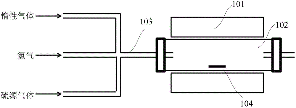
[0040] As an example, the structure of the chemical vapor deposition reaction chamber is figure 1 As shown, the tube furnace 101, the quartz tube 102, and the air passage 103 are included.
[0041] As an example, the graphene 104 is placed in the reaction chamber with a metal substrate as a carrier. After step 2), it further includes step a) S13, in which hydrogen gas is fed into the reaction cha...
Embodiment 2
[0049] Such as figure 1 and Figure 4 As shown, this embodiment provides a method for sulfur doping graphene, which at least includes the following steps:
[0050] First, perform step 1) S21, provide graphene, and place the graphene in a chemical vapor deposition reaction chamber;
[0051] Then proceed to step 2) S22, using inert gas to vent and exhaust the reaction chamber;
[0052] Then proceed to step 3) S23, introducing a sulfur source gas at 500-1050°C to dope the graphene with sulfur;
[0053] Finally, step 4) S24 is performed to cool the reaction chamber in a hydrogen and inert gasatmosphere.
[0054] As an example, the structure of the chemical vapor deposition reaction chamber is figure 1 As shown, the tube furnace 101, the quartz tube 102, and the air passage 103 are included.
[0055] As an example, in step 1), the graphene 104 is placed in the reaction chamber using a silicon substrate with an insulating layer as a carrier. The graphene on the insulating substrate is direct...
PUM
Abstract
The invention provides a sulfurdoping method for graphene. The method comprises the steps of: 1) providing graphene and placing the grapheme in a chemical vapor depositionreaction chamber; 2) employing an inert gas to conduct ventilation and exhaust treatment on the reaction chamber; 3) introducing a sulfur source gas to perform sulfurdoping on the graphene at 500-1050DEG C; and 4) cooling the reaction chamber in a hydrogen and inert gas atmosphere. The method provided by the invention can perform sulfur doping on the graphene simply and efficiently, the economic cost is low, and large-scale production can be realized. Large area sulfur doping on graphene can be realized, and doping of graphene on an insulating substrate or metal substrate can be carried out directly, thus facilitating making of sulfur doped graphene devices. In the preparation process, the sulfur doping concentration can be controlled by adjusting the sulfur source gas flow, thereby realizing controllable doping on graphene.
Description
Technical field [0001] The invention belongs to the technical field of materials, and in particular relates to a method for sulfur doping graphene. Background technique [0002] Graphene is a planar monoatomic layer film material formed by carbon atoms arranged in a two-dimensional regular hexagonal honeycomb lattice. Since graphene has outstanding thermal conductivity and mechanical properties, high electron mobility, half-integer quantumHall effect and other properties, since it was first discovered in 2004, graphene has attracted widespread attention from the scientific community and set off a wave Research boom. [0003] Graphene is made of sp 2 The single-layer planar graphite with hybridcarbon atom bonding and a two-dimensional hexagonal lattice honeycomb structure has extremely high crystal quality and electrical properties. As a strict two-dimensional crystal material, graphene has unique physical properties, with a carrier concentration of up to 1013 cm -2 , The mobili...
Claims
Application Information
Patent Timeline
Application Date:The date an application was filed.
Publication Date:The date a patent or application was officially published.
First Publication Date:The earliest publication date of a patent with the same application number.
Issue Date:Publication date of the patent grant document.
PCT Entry Date:The Entry date of PCT National Phase.
Estimated Expiry Date:The statutory expiry date of a patent right according to the Patent Law, and it is the longest term of protection that the patent right can achieve without the termination of the patent right due to other reasons(Term extension factor has been taken into account ).
Invalid Date:Actual expiry date is based on effective date or publication date of legal transaction data of invalid patent.
Patent Type & Authority Patents(China)
IPC IPC(8): C30B31/08
Inventor 梁晨李铁王跃林
Owner SHANGHAI INST OF MICROSYSTEM & INFORMATION TECH CHINESE ACAD OF SCI

