A Tunable Slab Laser

A strip laser and optical path technology, which is applied in the field of lasers to achieve the effects of simple structure, reasonable design and easy realization

Active Publication Date: 2017-12-26
成都精密光学工程研究中心
View PDF3 Cites 0 Cited by
  • Summary
  • Abstract
  • Description
  • Claims
  • Application Information

AI Technical Summary

Problems solved by technology

[0005] The purpose of the present invention is to provide a tunable slab laser, aiming at solving the problem of improving the output power of the miniaturized tunable slab laser

Method used


Image

  • A Tunable Slab Laser
  • A Tunable Slab Laser
  • A Tunable Slab Laser

Examples


Embodiment 1

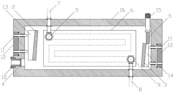
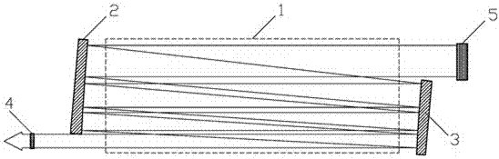
[0031] A tunable slab laser, including a vacuum cavity, the vacuum cavity is an all-metal structure. In this embodiment, the material is aluminum, which has good heat dissipation, light weight, and heat treatment during processing to reduce deformation. The radio frequency power supply is connected to the upper and lower walls of the inner wall of the vacuum chamber through a transmission line to form a waveguide cavity. An optical path folding system is arranged horizontally in the vacuum chamber, and the optical path folding system includes a reflective blazed grating, a total reflection concave mirror, a total reflection convex mirror and a partial reflection output mirror. The reflective blazed grating and the total reflection convex mirror are installed on the inner surface of the vacuum chamber On the side wall of the total reflection concave mirror and the partial reflection output mirror are installed on the inner surface of the vacuum chamber on the side wall opposite ...

Embodiment 2

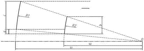
[0035] On the basis of Embodiment 1, the focal point O of the total reflection concave mirror and the total reflection convex mirror coincide (confocal), and the distance L2 between the confocal point O and the total reflection convex mirror is half of the radius of curvature R2 of the total reflection convex mirror , the distance L1 between the confocal point O and the total reflection concave mirror is half of the curvature radius R1 of the total reflection convex mirror, the specific design is as follows figure 2 shown. Such a design can make each folded optical path of the oscillating beam as close as possible to achieve the purpose of fully utilizing the gain working medium and improving laser efficiency. The outgoing light after the oscillating light is frequency-selected through the reflective blazed grating is parallel light, and the incident light that enters the partial reflection output mirror after being reflected by the total reflection convex mirror for the last...

Embodiment 3

[0037] On the basis of Embodiment 1 or Embodiment 2, two electrodes, upper and lower, are vertically arranged in the vacuum chamber. The electrodes can be made of aluminum or copper. In this embodiment, the electrode material is copper, and the upper electrode is close to the inside of the vacuum chamber. The top surface and the lower electrode are close to the bottom surface of the vacuum cavity. The distance between the upper and lower electrodes is 1~3mm. The two electrodes are connected to the RF power supply through the transmission line and form a gain interval between the electrodes.


PUM


Abstract

The invention discloses a tunable slab laser, and belongs to the technical field of lasers. The tunable slab laser aims at improving the output power of a small tunable slab laser. According to the technical scheme, the tunable slab laser comprises a vacuum cavity. A laser path folding system is transversely arranged in the vacuum cavity and comprises a reflection-type blazed grating, a total-reflection concave mirror, a total-reflection convex mirror and a partial-reflection output mirror. After frequency selecting is carried out on oscillation lasers through the blazed grating, the oscillation lasers sequentially pass through the total-reflection concave mirror and the total-reflection convex mirror and are reflected by the total-reflection concave mirror and the total-reflection convex mirror, and finally the reflected lasers are output through the partial-reflection output mirror. The structure is mainly used for the laser, the quality of output laser beams of the laser can be guaranteed, the power density on the grating face can be reduced, and larger power output can be achieved.

Description

technical field [0001] The invention relates to a tunable slab laser, in particular to a tunable slab laser capable of realizing relatively high power output, and belongs to the technical field of lasers. Background technique [0002] Tunable lasers are generally divided into two categories: a medium-based broadband emission spectrum combined with frequency-selective technology to achieve continuous tuning of the laser oscillation wavelength, dye lasers, tunable excimer lasers, high-pressure gas lasers, solid transition metal ion lasers, and color lasers. Center lasers, tunable semiconductor lasers, free electron lasers, etc. all belong to this category; the other category is to obtain a continuously adjustable wavelength optical parameter process through a nonlinear optical optical parameter process for a certain fixed wavelength laser or tunable laser. Laser technology, such as optical parametric oscillation technology, optical parametric amplification technology, tunable ...

Claims


Application Information

Patent Timeline
Patent Type & Authority Patents(China)
IPC IPC(8): H01S3/081H01S3/042
Inventor 王度周逊李赜宇罗振飞孔维鹏李光彬邹明芮
Owner 成都精密光学工程研究中心
Why Eureka
Try Eureka