Ceramic catalyst carrier

A ceramic catalyst and ceramic technology, which is applied in the direction of catalyst carrier, physical/chemical process catalyst, chemical instrument and method, etc., can solve the problems of low efficiency, reduced efficiency, uneven mixing of ammonia gas/nitrogen oxide, etc., and reduce the use of cost, life extension, and safety risk reduction effects

Inactive Publication Date: 2014-10-01
ZIBO WANMA CERAMIC DESIGN CO LTD
View PDF3 Cites 0 Cited by
  • Summary
  • Abstract
  • Description
  • Claims
  • Application Information

AI Technical Summary

Problems solved by technology

3. Selective non-catalyst reduction technology (SNCR), mainly used in small and medium-sized boilers such as waste incineration, the technology is mature, but its efficiency is lower than that of the SCR method, the investment is small, and the construction period is short
About 20-25% of the exhaust smoke generated in the furnace falls between the furnace and the air preheater. Taking the honeycomb catalyst as an example, if the catalyst gap is too small, it will cause fly ash to block, thereby preventing the flue gas and Catalyst contact, reduced efficiency, increased wear
And increasing the pore size will reduce the contact area between the flue gas and the catalyst, reducing the denitrification efficiency
The denitrification efficiency of the flue gas denitration device is affected by the uniformity of the flue gas flow velocity distribution and the reducing agent ammonia (NH 3 ) / nitrogen oxides (NO X ) Mixing uniformity has a great influence, such as uneven flow rate distribution, or uneven mixing of ammonia gas / nitrogen oxides, which will greatly reduce the denitrification efficiency, cause ash blocking, and even cause the boiler to trip and shut down, which will bring a negative impact on the safety of the power plant. also cause great economic losses

Method used


Image

  • Ceramic catalyst carrier
  • Ceramic catalyst carrier

Examples


Embodiment

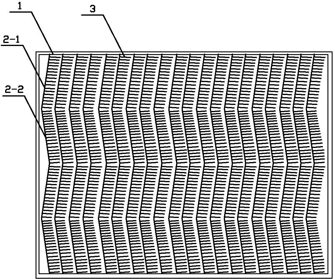
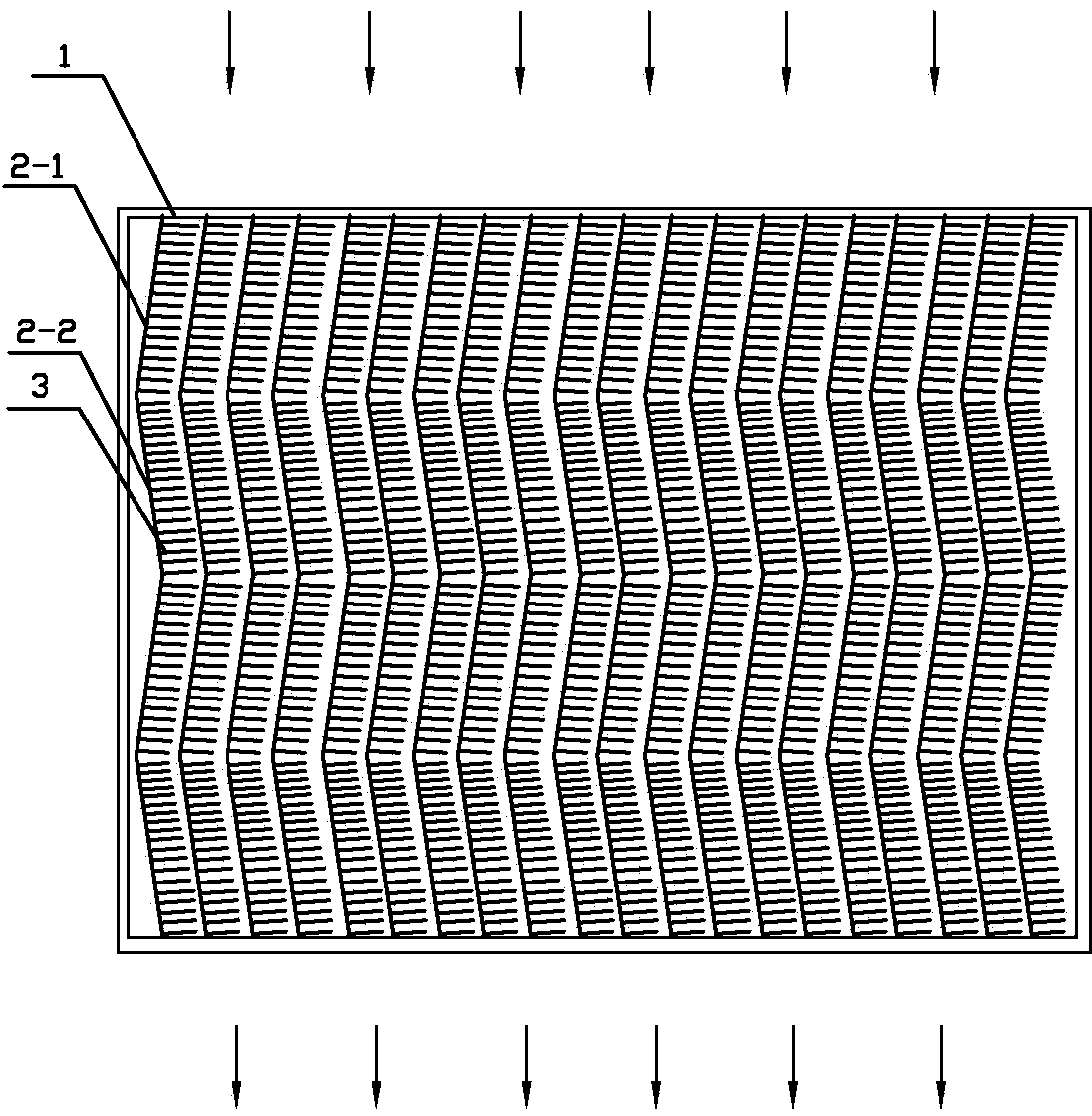
[0027] Such as figure 1 The ceramic catalyst carrier shown includes a support frame 1, and a herringbone ceramic wave plate is arranged side by side inside the support frame 1, and the herringbone ceramic wave plate is divided into a first ceramic wave plate 2-1 and a second ceramic wave plate 2-2; Hair-shaped ceramic rods 3 are set on a ceramic wave plate 2-1, and each hair-shaped ceramic rod 3 is perpendicular to the first ceramic wave plate 2-1; hair-shaped ceramic rods 3 are set on the second ceramic wave plate 2-2, and each hair-shaped ceramic rod 3 is perpendicular to the first ceramic wave plate 2-1; The hair-like ceramic rod 3 is perpendicular to the second ceramic wave plate 2-2.

[0028] The angle between the first ceramic wave plate 2-1 and the second ceramic wave plate 2-2 is 130-160°.

[0029] The herringbone ceramic wave plate and the hair-shaped ceramic rod 3 are collectively referred to as the hair-shaped herringbone ceramic group carrier.

[0030] 2-5 hair-s...


PUM

PropertyMeasurementUnit
angleaaaaaaaaaa
denitrification rateaaaaaaaaaa

Abstract

The invention belongs to the field of catalysts and particularly relates to a ceramic catalyst carrier. The ceramic catalyst carrier comprises a support frame, wherein herringbone ceramic wave plates are arranged in the support frame side by side and comprise first ceramic wave plates and second ceramic wave plates; hair-shaped ceramic bars are arranged on the first ceramic wave plates and the second ceramic wave plates, and are respectively vertical to the first ceramic wave plates and the second ceramic wave plates. According to the ceramic catalyst carrier, the time for smoke to pass through the surface of the catalyst is prolonged; the clogging rate and the dust carrying rate are reduced, the pressure drop is small, security risks of a boiler main engine and an induced draft fan are reduced; the ceramic catalyst carrier is high in mechanical strength and is corrosion-resistant and wear-resistant, the repair rate of the catalyst is reduced, the service life is prolonged, and the use cost is lowered; the ceramic catalyst carrier is exclusively used in the atmospheric environment treatment.

Description

technical field [0001] The invention belongs to the field of catalysts, and in particular relates to a ceramic catalyst carrier. Background technique [0002] Thermal power plants are the main source of nitrogen oxide air pollution emissions. At present, there are roughly four main methods to reduce NOX emissions from coal-fired boilers in thermal power plants in the world: 1. Low-nitrogen combustion technology, that is, to control the formation of nitrogen oxides during the combustion process, which is mainly applicable to large-scale coal-fired boilers. low NO X Combustion technology can only reduce NO X 30-50% of the emission value. 2. Selective catalyst reduction technology (SCR), mainly used in large coal-fired boilers, is currently the most widely used flue gas denitrification technology in my country. 3. Selective non-catalyst reduction technology (SNCR), which is mainly used in small and medium-sized boilers such as waste incineration, has mature technology, but ...

Claims


Application Information

Patent Timeline
Patent Type & Authority Applications(China)
IPC IPC(8): B01J32/00B01J35/02
Inventor 冯延泉孙伟王延宏马恒艳高森
Owner ZIBO WANMA CERAMIC DESIGN CO LTD
Why Eureka
Try Eureka