Solar generator platform

A solar panel and platform technology, applied in the field of solar generator arrays, to achieve the effect of firm and stable platform

Inactive Publication Date: 2014-10-08
POWERAK
View PDF19 Cites 15 Cited by
  • Summary
  • Abstract
  • Description
  • Claims
  • Application Information

AI Technical Summary

Problems solved by technology

[0028] · No commercial product available that can be adapted to meet US EPALT2 regulations
[0029] Land-based arrays and systems designed for installation on rooftops or buildings lack the ability to be easily and inexpensively installed

Method used


Image

  • Solar generator platform
  • Solar generator platform
  • Solar generator platform

Examples


no. 1 approach

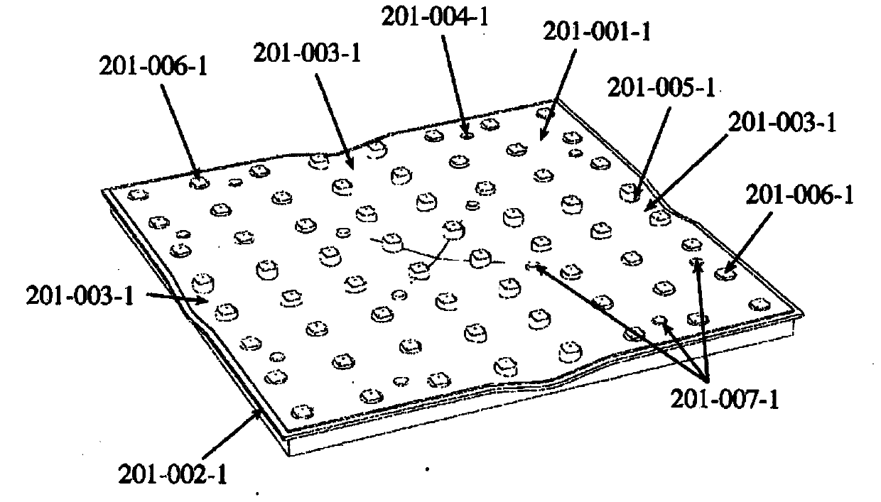
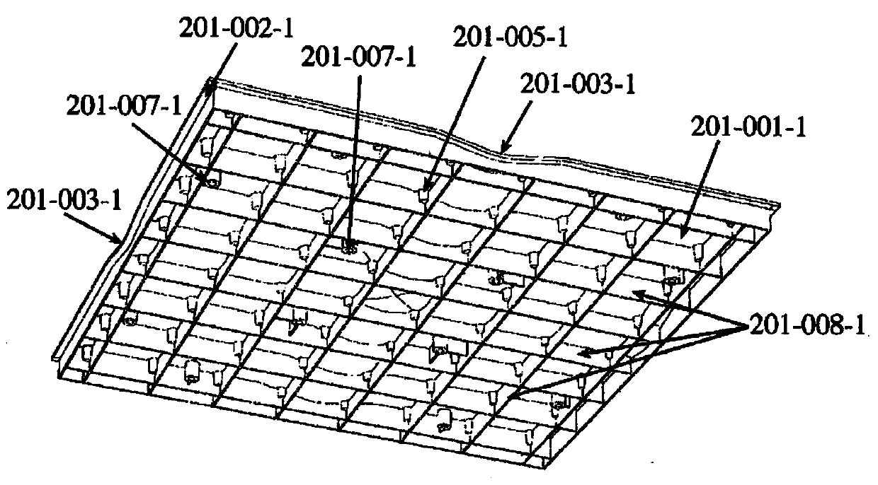
[0223] In a first embodiment, the deck comprises a peripheral extrusion [201-002-1, figure 1 , figure 2 , Figure 20 ], wherein each deck perimeter extrusion is inserted into a seal when the deck array is assembled [202-001-1, Figure 19 with Figure 20 ], said seal extending parallel to each of said deck perimeter extrusions [2002] and between said deck perimeter extrusions [2002]. Peripheral extrusions are molded to follow the contours of the deck surface [201-002-1, figure 1 with figure 2], thereby connecting and continuing to form a drainage system in the plane X and Y directions, and extending to the periphery of the array. The seal provides a compressible watertight connection between adjacent deck first embodiments. Where the four decks meet, specific four arm compressive seals [204-001-1, Figure 18 ] with waterproof extrusion [204-004-1, Figure 18 ], wherein at said arm extruded compressive seal, a watertight insert [204-002-1, Figure 18 ] slides into the...

Embodiment approach 301-001-2

[0227] (1) produce a displacement equal to the equivalent of the combined payload;

[0228] (2) Compress trapped air according to cavity air temperature and weight of combined load. While said air compression will provide some vertical movement, thereby relieving pressure if the deck is subjected to lift, the trapped air will reach an equilibrium pressure point beyond which water flowing into the cavity will act as a lift damper. The function of the vibrator. Thereby virtually suppressing the effect of the sudden lift, noting that for large deployments the sudden lift can be a huge number.

[0229] Squeeze boss on top of first embodiment of invert [301-004-1, Figure 5 with Figure 10 ] are placed via bolts [202-001-1, Figure 10 ] accepts the fixing from the deck, thereby providing fixation between the inverted piece and the deck. Peripheral Male Connector at Base of Inversion [301-003-1, Figure 5 with Image 6 ] Supply with Receiver [301-002-1 Figure 5 with Image...


PUM


Abstract

An assembly of, uniquely inter-connected modular parts form a high strength waterproof flexible membrane. The said membrane is restrained / positioned in the horizontal plane via a perimeter beam, with fixings on its exterior boundary to the storage parapet / berm, and through internal tendons to the PV panel super structure rows, whilst allowing unrestricted vertical movement in concert with the water level changes. This invention is intended to provide stability, reliability and durability under localised extreme weather conditions. The system may be mounted on a flotation pod or on a land based or building structure.

Description

[0001] The present invention relates to a solar generator array formed flat on an assembly of modular components interconnected in a unique manner to form a high strength waterproof flexible membrane. This can be water based or land based construction. The membrane is secured to the tank guardrail / steps via ring beams with fixtures on the outer boundary of the ring beams and is constrained in the horizontal plane by inner ribbing while allowing for unrestricted movement in line with changes in water level. Constrained vertical movement. The present invention is intended to provide stability, reliability and durability under endemic extreme weather conditions. [0002] The present invention improves evaporation and / or water quality of storage ponds via partial or full coverage, while providing a strong stable platform for solar power generation. Background technique [0003] For some time there has been an interest in covering water storage tanks to reduce evaporation and to ...

Claims


Application Information

Patent Timeline
Patent Type & Authority Applications(China)
IPC IPC(8): H02S20/24H02S20/25E04D13/18B63B35/44B65D88/34
CPCF24J2/5239F24J2/5241F24J2/526H01L31/0482F24J2/5237Y02E10/50H01L31/0422B63B2035/4453E04D11/005F24J2/5256F24J2/5267H02S20/23H02S20/00B63B3/48Y02B10/12Y02B10/20Y02E10/47H02S20/10H02S20/30F24S25/11F24S25/65F24S25/50F24S25/634F24S25/16F24S20/70F24S30/40F24S30/20Y02B10/10
Inventor G·J·卡普R·伍德菲尔德
Owner POWERAK
Why Eureka
Try Eureka