Continuous distillation technology used for regeneration of spent lubrication oil

A technology of waste lubricating oil and process, which is applied in the direction of lubricating composition, etc., can solve the problems of incorporation and complicated process, and achieve the effect of good technical and economical efficiency

Inactive Publication Date: 2014-10-15
四川省中明环境治理有限公司 +1
View PDF12 Cites 17 Cited by
  • Summary
  • Abstract
  • Description
  • Claims
  • Application Information

AI Technical Summary

Problems solved by technology

[0014] Since the above-mentioned patents still have problems such as complex process, doping of other metals or inorganic ions, etc.

Method used


Image

  • Continuous distillation technology used for regeneration of spent lubrication oil
  • Continuous distillation technology used for regeneration of spent lubrication oil
  • Continuous distillation technology used for regeneration of spent lubrication oil

Examples


Embodiment 1

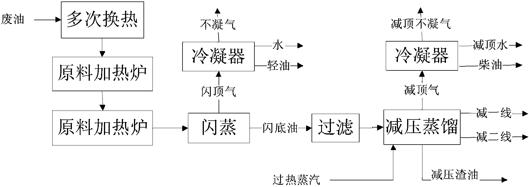
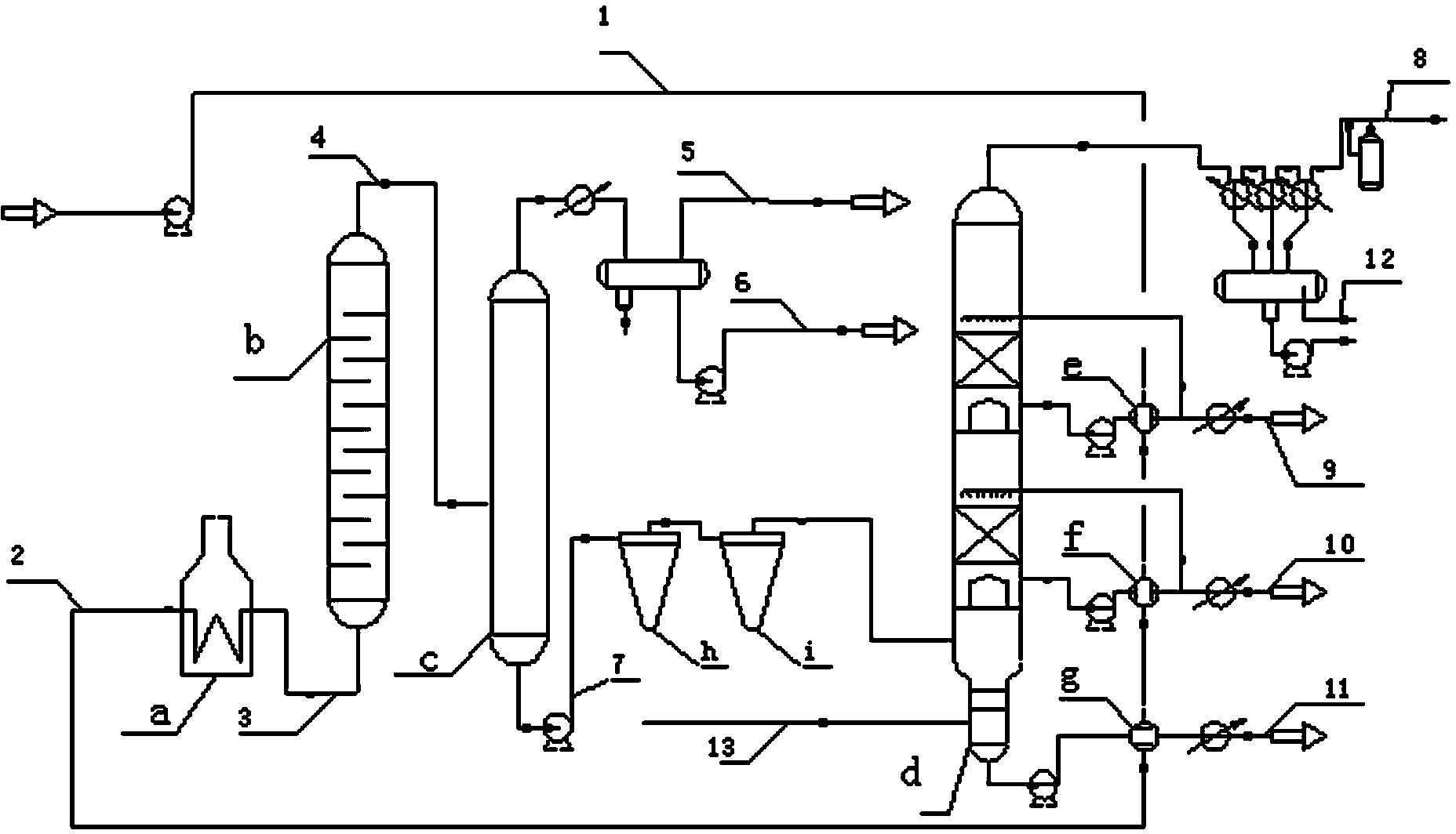
[0033] Embodiment 1: as figure 2 As shown, lubricating oil 1 coming from the tank area with a normal temperature of about 40°C and a flow rate of 12875kg / h conducts heat exchange with the fraction extracted from the side line of the minus line first in the raw oil-light base oil heat exchanger e, and then exchanges heat with the side line of the minus line The raw material oil-heavy base oil heat exchanger f performs heat exchange, and finally performs heat exchange with the raw material oil-vacuum residue heat exchanger g at the bottom of the vacuum tower to obtain stream 2, whose temperature is 240°C.

[0034] Stream 2 enters the feed heating furnace a and is heated to obtain stream 3 at 380°C. Stream 3 enters vis-reducing reaction tower b. The operating conditions are: temperature 380°C, residence time 1h.

[0035] The waste oil 4 after visbreaking heat treatment has a temperature of 377° C., and it directly enters the flash tower c for flash evaporation at an operating pr...

Embodiment 2

[0037] Example 2: The waste lubricating oil 1 from the tank farm at a normal temperature of about 40°C is first exchanged with the fraction extracted from the side line of the first line in the raw material oil-light base oil heat exchanger e, and then exchanged with the raw material oil of the side line of the second line reduction- The heavy base oil heat exchanger f performs heat exchange, and finally conducts heat exchange with the raw material oil at the bottom of the vacuum tower—vacuum residue heat exchanger g to obtain stream 2, whose temperature is 280°C.

[0038] Stream 2 enters the feed heating furnace a and is heated to obtain stream 3 at 320°C. Stream 3 enters vis-reducing reaction tower b. The operating conditions are: temperature 320°C, residence time 1.5h.

[0039] The waste oil 4 after visbreaking heat treatment has a temperature of 318° C., and it directly enters the flash tower c for flash evaporation at an operating pressure of 1 MPa. The top of the tower i...

Embodiment 3

[0041] Example 3: The normal temperature waste lubricating oil 1 from the tank area is first exchanged with the fraction extracted from the side line of the first line reduction in the raw material oil-light base oil heat exchanger e, and then exchanged with the raw material oil of the second line side line reduction-heavy base oil The heat exchanger f performs heat exchange, and finally exchanges heat with the raw material oil at the bottom of the vacuum tower—the vacuum residue heat exchanger g to obtain stream 2, whose temperature is 260°C.

[0042] Stream 2 enters the feed heating furnace a to be heated to obtain stream 3 at 350°C, and stream 3 enters vis-reducing reaction tower b. The operating conditions are: temperature 350°C, residence time 1h.

[0043] The waste oil 4 after visbreaking heat treatment has a temperature of 346°C, and it directly enters the flash tower c, where it is flashed at an operating pressure of 1 MPa. The top of the tower is condensed and separat...


PUM


Abstract

The invention discloses a continuous distillation technology used for regeneration of spent lubrication oil. The continuous distillation technology includes a heat exchange process of the spent lubrication oil and distilled cut fraction, a visbreaking heat treatment process and a flash distillation-reduced pressure distillation process. By means of visbreaking heat treatment, clean dispersing additives in the spent lubrication oil can be broken down effectively to enable suspended impurities such as metal in the spent lubrication oil to be deposited more easily, and part of metal salt additives and corrosive organic acid can be decomposed or deteriorated. By means of flash distillation-reduced pressure distillation, light components and base oil fractions can be pulled out effectively. Additionally, an optimized heat exchange system is capable of lowering energy consumption caused by continuous distillation, the total pull-out rate of the technological spent lubrication oil is more than 85%, the continuous distillation technology is good in technological economy, low in impurity content (particularly in metal content), and distilled products can serve as quality raw materials for subsequent hydrofining directly.

Description

technical field [0001] The invention belongs to the technical fields of refining and chemical engineering, environmental protection and energy, and relates to a pollution-free recycling method of waste lubricating oil and an oil refining process for producing lubricating oil base oil from waste oil as a refining raw material. Background technique [0002] In waste oil regeneration, distillation, as an important unit process, can be used not only for dehydration in waste oil purification, but also for light deoiling in re-refining, and to divide waste lubricating oil into several base oil fractions, and also Asphaltene, colloids, additives, metal salts, etc. in waste oil can be left in the distillation residue and separated from the base oil. [0003] There are a large number of solid particles in lubricating oil, such as worn metal particles, carbon particles generated by combustion, mechanical impurities, cleaning and dispersing agents dispersed in waste oil, functional add...

Claims


Application Information

Patent Timeline
IPC IPC(8): C10M175/00
Inventor 柳云骐韩海陈小军王玉龙马海灵何中明
Owner 四川省中明环境治理有限公司
Why Eureka
Try Eureka