Waste heat recovery furnace

A waste heat recovery and cooling cylinder technology, applied in furnaces, waste heat treatment, furnace components, etc., can solve problems such as serious air leakage of coolers, loss of sintered ore, and increased power of assembly fans, so as to reduce power consumption and fully heat Exchange, the effect of small power

Active Publication Date: 2016-04-13
TIANJIN ZHENGYUANHE TECH DEV CO LTD
View PDF7 Cites 1 Cited by
  • Summary
  • Abstract
  • Description
  • Claims
  • Application Information

AI Technical Summary

Problems solved by technology

[0005] First of all, because the design of the cooler only focuses on the cooling of sinter, and the waste heat recovery device is a follow-up supplement, so in order to facilitate heat dissipation, cooling is usually carried out in an open space. The air leakage of the cooler is serious, and a large amount of waste heat of sinter is lost along with the air leakage. environment, so the sintering waste heat cannot be effectively utilized
At the same time, due to the existence of air leakage, the amount of cold air used to cool the waste heat of sintered ore is increased, so the power of the assembly fan is increased, which is not conducive to energy saving
[0006] Secondly, because the cooler only focuses on the cooling of high-temperature sinter rather than waste heat recovery, the cooler uses a large-volume fan to cool the sinter on the trolley. The material layer thickness of the trolley is relatively low, and the air supply by the fan is very uneven. In order to ensure that the rear belt will not be burned after the temperature is lowered, excessive cooling is required. The waste heat recovery is only based on this type of device. A coil and steam for absorbing the hot gas formed by cooling the sinter are added to the upper part of the cooler. package, so the recycling efficiency is not high
Moreover, the distribution of cooling air at the bottom is unreasonable, and the material is not cooled uniformly, resulting in an increase in the amount of cooling air used to cool the material, thereby increasing the power of the cooling fan.

Method used


Image

  • Waste heat recovery furnace
  • Waste heat recovery furnace

Examples


Embodiment Construction

[0026] Hereinafter, the waste heat recovery furnace as the present invention will be described based on the drawings.

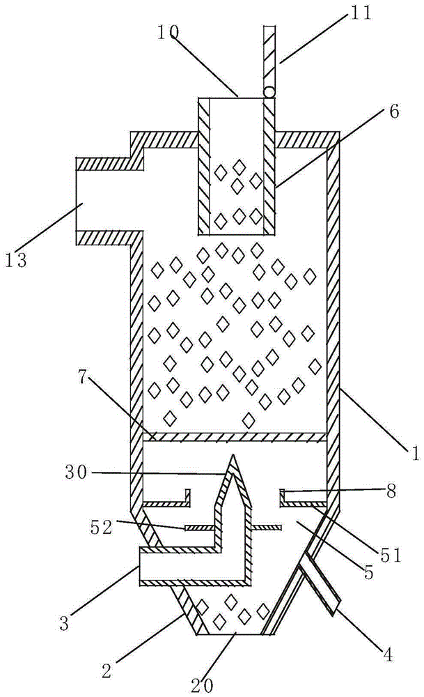
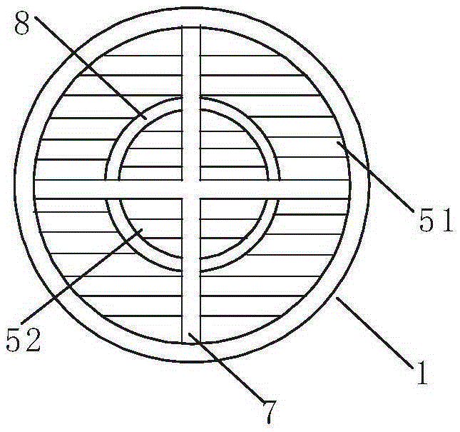
[0027] figure 1 It is a schematic cross-sectional view showing the waste heat recovery furnace of the present invention. figure 2 A schematic plan view showing the discharge mechanism of the waste heat recovery furnace of the present invention.

[0028] Such as figure 1 As shown, the waste heat recovery furnace of the present invention has a cooling cylinder 1, a feed port 10 is provided on the upper surface of the cooling cylinder 1, and a sealing cover 11 that seals the feed port is arranged at the feed port 10. An air outlet 13 is formed on the side wall of the upper end of the cylinder 1, and the air outlet 13 is connected to an induced draft fan (not shown).

[0029] A cone-shaped cold silo 2 is connected to the lower end of the cooling cylinder 1, a discharge port 20 is formed at the lower end of the cold silo 2, and a vibration discharger (not shown) is ins...


PUM


Abstract

The invention provides a waste heat recycling furnace. According to the waste heat recycling furnace, waste heat of sintered ore can be sufficiently and efficiently recycled. The waste heat recycling furnace comprises a cooling cylinder. A feeding opening is formed in the upper surface of the cooling cylinder, a sealing cover for sealing the feeding opening is arranged on the feeding opening, an air outlet is formed in the upper end of the side wall of the cooling cylinder and connected with an induced draft fan, a conical cold feeder is connected to the lower end of the cooling cylinder, a discharging opening is formed in the lower end of the cold feeder, a vibration discharging machine is installed in the discharging opening, a center cooling air pipe extending to the center of the cooling cylinder is installed on the waste heat recycling furnace, a conical center air cap with the upward top end is connected to the upper end of the center cooling air pipe, a plurality of air holes are formed in the conical wall of the center air cap, one or more peripheral cooling air pipes are formed on the conical wall of the cold feeder in the mode of surrounding the conical wall, a discharging mechanism is arranged between the cooling cylinder and the cold feeder and comprises an upper discharging plate and a lower discharging plate, and the upper discharging plate and the lower discharging plate can be opened and closed and can achieve discharging through reciprocating movement.

Description

Technical field [0001] The invention relates to a waste heat recovery furnace. Background technique [0002] At present, steel has become an indispensable material in people's life and production, and the steel used in modern life is mainly obtained from iron ore. In the process of smelting, in order to fully react the iron ore to produce as much steel as possible, it is usually necessary to crush and screen the iron ore. Since the crushed ore powder is not easy to be smelted in a furnace, it needs to be sintered into a block. , Spherical shape, and then loaded into the furnace for smelting. [0003] The existing sintering process in the iron and steel industry includes batching, sintering, cooling, screening and other processes. Among them, the cooling process after the completion of the sintering process mainly uses process equipment such as ring cooling and band cooling to make the material temperature of the sintered ore change from 700 ℃ Decrease to 100 to 180°C. [0004] Jud...

Claims


Application Information

Patent Timeline
Patent Type & Authority Patents(China)
IPC IPC(8): F27D17/00
CPCY02P80/15
Inventor 白银川
Owner TIANJIN ZHENGYUANHE TECH DEV CO LTD
Why Eureka
Try Eureka