Pulse modulation signal phase noise measuring device and method

A technology of pulse modulation signal and phase noise, which is applied in the field of pulse modulation signal phase noise measurement and pulse modulation signal phase noise measurement device, and can solve problems such as affecting phase noise measurement and decreasing system sensitivity.

Active Publication Date: 2014-10-29
THE 41ST INST OF CHINA ELECTRONICS TECH GRP
View PDF6 Cites 18 Cited by
  • Summary
  • Abstract
  • Description
  • Claims
  • Application Information

AI Technical Summary

Problems solved by technology

If this voltage cannot be eliminated, the back-end amplifier will quickly enter a saturated state, resulting in a decrease in system sensitivity
When the reference source is continuous wave, all the amplitude modulation noise of the local oscillator signal will be transferred to the IF port, and only part of the phase noise will be transferred. Although the amplitude modulation noise of the reference source is usually much lower than the phase noise, as The reduction of the duty cycle of the pulse modulation signal, the two will gradually approach and eventually affect the measurement of phase noise
In order to eliminate the unfavorable factors brought by the continuous wave phase detection to the phase noise measurement, the pulse reference source is usually used as the local oscillator, which can effectively suppress the deterioration of the DC offset and amplitude modulation noise, but it still needs to solve the problem between the measured signal and the reference source. pulse synchronization problem

Method used


Image

  • Pulse modulation signal phase noise measuring device and method
  • Pulse modulation signal phase noise measuring device and method
  • Pulse modulation signal phase noise measuring device and method

Examples


Embodiment Construction

[0061] The following will clearly and completely describe the technical solutions in the embodiments of the present invention with reference to the accompanying drawings in the embodiments of the present invention. Obviously, the described embodiments are only some, not all, embodiments of the present invention. Based on the embodiments of the present invention, all other embodiments obtained by persons of ordinary skill in the art without making creative efforts belong to the protection scope of the present invention.

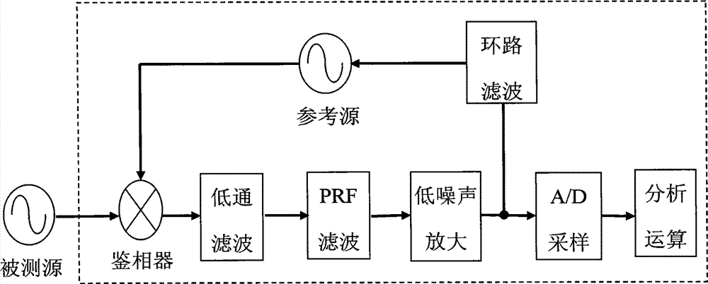
[0062] Since the phase detection method suppresses the carrier wave through the quadrature phase detection method, the instantaneous voltage fluctuation of the intermediate frequency output is linearly related to the instantaneous phase fluctuation of the input signal, which solves the problem of large deviation of the measurement results when the intermediate frequency leakage causes a small frequency deviation; combined with The low-noise amplifier can make f...


PUM


Abstract

The invention provides a pulse modulation signal phase noise measuring device. The pulse modulation signal phase noise measuring device comprises a down conversion and orthogonal phase discrimination arithmetic unit, wherein the down conversion and orthogonal phase discrimination arithmetic unit comprises a down conversion unit, an orthogonal phase discrimination unit and a sampling arithmetic unit, which are sequentially arranged from an input end to an output end, the down conversion unit comprises a local oscillator, a frequency mixer, a tunable band pass filter and a primary low noise amplification unit, the orthogonal phase discrimination unit comprises a phase discriminator, a low pass filter, a secondary low noise amplification unit, a loop filter and a reference source, the sampling arithmetic unit comprises an A/D (analog to digital) sampling unit and an analysis and arithmetic unit, and a phase noise measuring result is obtained after an output signal of the orthogonal phase discrimination unit passes through the A/D sampling unit and the analysis and arithmetic unit. The pulse modulation signal phase noise measuring device decreases numbers of needed test instruments and electric cables, simplifies measurement steps, and reduces test difficulty.

Description

technical field [0001] The invention relates to the technical field of testing, in particular to a pulse modulation signal phase noise measurement device, and also to a pulse modulation signal phase noise measurement method. Background technique [0002] Phase noise is an important indicator for evaluating the short-term stability of signal frequency. The performance of phase noise has an important impact on the overall performance of electronic systems, such as the range of radar systems, target resolution, bit error rate of digital communication systems, and image signals. Indexes such as quality, satellite positioning accuracy, and signal interference between adjacent channels of the receiver system are all related to the carrier phase noise of the system frequency source. [0003] Because pulse modulation signals have strong communication security and anti-interference performance, they have been widely used in secure communication systems and radar equipment. Most of th...

Claims


Application Information

Patent Timeline
Patent Type & Authority Applications(China)
IPC IPC(8): G01R29/26
Inventor 杜念文白轶荣刘宝东李伟丁建岽
Owner THE 41ST INST OF CHINA ELECTRONICS TECH GRP
Why Eureka
Try Eureka