Light hydrocarbon separation device and method for liquefied natural gas

A technology of liquefied natural gas and separation device, applied in the field of light hydrocarbon recovery, can solve the problems of high equipment cost, high pressure, unfavorable storage and transportation, and substandard product concentration.

Active Publication Date: 2015-12-02
XI'AN PETROLEUM UNIVERSITY +1
View PDF11 Cites 0 Cited by
  • Summary
  • Abstract
  • Description
  • Claims
  • Application Information

AI Technical Summary

Problems solved by technology

The power consumption of the compressor is relatively large compared with other equipment, resulting in excessive power consumption of the system, which is not conducive to the economic benefits of the device;
[0008] 2) Some processes use complex heat exchange pipe networks to reduce energy consumption, but the structure is complex, the design is highly targeted but the adaptability is poor, the investment cost is too high, and the investment risk coefficient of the enterprise is increased;
[0009] 3) The separated methane is all liquid and needs to be gasified before it can be input into the natural gas pipeline network system, and a large amount of fuel is required during the gasification process, which increases the operating cost of the device;
[0010] 4) Some processes can only extract methane, and for C in LNG 2 + The components have not been processed, and the resources hidden in LNG have not been maximized;
[0011] 5) C obtained by certain processes 2 + Excessive pressure is not conducive to storage and transportation, increases the difficulty of product handling, and is not conducive to the management of petrochemical enterprises
However, most of these processes have the following criticisms, such as complex structure, high equipment cost and substandard product concentration, etc.

Method used


Image

  • Light hydrocarbon separation device and method for liquefied natural gas
  • Light hydrocarbon separation device and method for liquefied natural gas
  • Light hydrocarbon separation device and method for liquefied natural gas

Examples


Embodiment 1

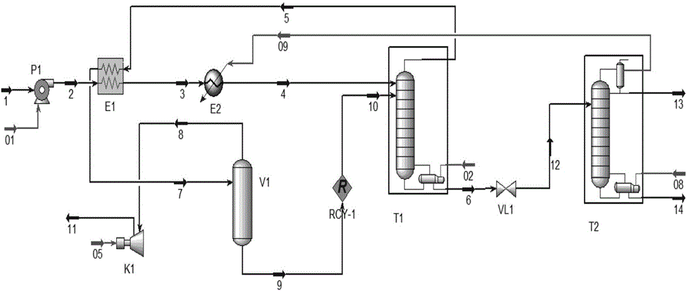
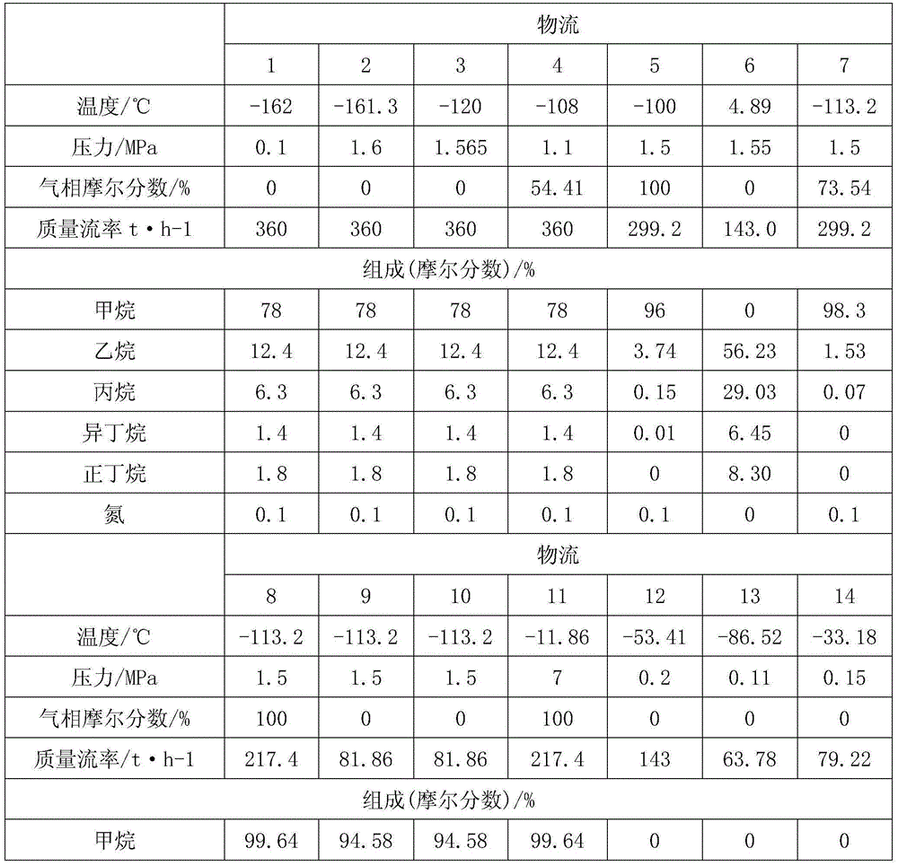
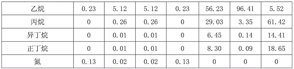
[0048] The processing capacity is 360t / h, the LNG temperature is -162°C, normal pressure, and the molar content is: methane 78%, ethane 12.4%, propane 6.3%, isobutane 1.4%, n-butane 1.8%, nitrogen 0.1%.

[0049] Atmospheric LNG raw material is first boosted to 1.6MPa by pump P1, and then flows through heat exchangers E1 and E2 for heating twice. The heated LNG raw material is partially gasified, and its gas phase mole fraction is about 50%. The partially vaporized LNG enters the demethanizer T1, which operates at a pressure of 1.5 MPa. Methane-enriched natural gas with a methane mole fraction of 98.3% is obtained at the top of the column by separation, and this stream enters the flash tower V1 for further separation after heat exchange with the LNG feed in the heat exchanger E1. Liquid phase C is obtained at the bottom of the demethanizer 2 + Light hydrocarbons, of which the molar content of ethane is about 56%, and the remainder is C 3 + light hydrocarbons. The stream is...

Embodiment 2

[0059] The processing capacity of the device is 1 million tons per year, the LNG pressure is 0.8MPa, the temperature is -158°C, and the molar composition is as follows: methane 86.78%, ethane 8.13%, propane 3.67%, isobutane 0.55%, n-butane 0.55%, 0.05% isopentane, 0.05% n-pentane, 0.01% n-hexane, 0.22% nitrogen.

[0060] Atmospheric LNG raw material is first boosted to 3.8MPa by pump P1, and then heated twice through heat exchangers E1 and E2. The heated LNG raw material is partially gasified, and its gas phase mole fraction is about 20%. The partially vaporized LNG enters the demethanizer T1, which operates at a pressure of 3.6MPa. Methane-enriched natural gas with a methane mole fraction of 98% is obtained at the top of the tower by separation, and this stream enters the flash tower V1 for further separation after heat exchange with the LNG feed in the heat exchanger E1. Obtain the liquid phase C in the demethanizer tower kettle 2 + Light hydrocarbons, in which the molar ...

Embodiment 3

[0069] The processing capacity of the device is 1 million tons per year, the LNG pressure is 0.8MPa, the temperature is -158°C, and the molar composition is as follows: methane 91.15%, ethane 5.91%, propane 0.15%, isobutane 0.33%, n-butane 0.33%, Isopentane 0.01%, n-pentane 0.01%, n-hexane 0.01%, nitrogen 0.75%.

[0070] Atmospheric pressure LNG raw material is first boosted to 3.8MPa by pump P1, then flows through heat exchangers E1 and E2 for two heat exchanges and is partially gasified, and its gas phase mole fraction is about 6%. The partially vaporized LNG enters the demethanizer T1, which operates at a pressure of 3.6MPa. Methane-enriched natural gas with a methane mole fraction of 98% is obtained at the top of the tower by separation, and this stream enters the flash tower V1 for further separation after heat exchange with the LNG feed in the heat exchanger E1. The liquid phase C2+ light hydrocarbons are obtained in the bottom of the demethanizer, in which the molar co...


PUM


Abstract

The invention discloses a novel light hydrocarbon separation system and method for LNG. The system comprises an LNG pump, an outlet of the LNG pump is connected with a heating inlet of an LNG heat exchanger, a heating outlet of the LNG heat exchanger is connected with an inlet of a heater, and an outlet of the heater is connected with an inlet of a demethanizer. An outlet of the demethanizer is connected with a condensation inlet of the LNG heat exchanger, a condensation outlet of the LNG heat exchanger is connected with an inlet of a flash column, and an outlet in the top of the flash column (1) is connected with an inlet of a compressor. An outlet in the bottom of the flash column is connected with the inlet of the demethanizer. An outlet in the bottom of the demethanizer is connected with an inlet of a throttling valve. An outlet of the throttling valve is connected with an inlet of a dethanizer. The method includes the four steps of raw material preheating, demethanization, deethanization and circulating separation. Gaseous state methane which is separated from the top of the demetahnizer is partially liquefied, then a flash tank is used again, the product concentration is increased, the energy consumption of the whole separation system is reduced, ethane and C3+light hydrocarbon are recycled through LNG cold energy and made to be in a low-temperature and low-pressure state, and transportation and storage conditions of light hydrocarbon products are met.

Description

technical field [0001] The invention relates to the technical field of light hydrocarbon recovery, in particular to a light hydrocarbon separation device and method for liquefied natural gas. Background technique [0002] With the rapid development of the energy industry, people are paying more and more attention to the use of clean energy. Energy conservation, environmental protection, and high efficiency have become a major theme in today's energy industry. Since 2005, my country has been importing LNG, a new energy source with high calorific value and environmental protection, from abroad. In recent years, LNG receiving stations have been completed successively in China, marking the official arrival of the era of rapid development of my country's LNG industry. From 483 tons of LNG imports in 2005 to 17 million tons in 2013. There are also many problems behind the rapid development of the LNG industry. Through the investigation of LNG receiving stations, it is found tha...

Claims


Application Information

Patent Timeline
Patent Type & Authority Patents(China)
IPC IPC(8): C07C7/04C07C9/04C07C9/06C07C9/08
CPCF25J3/0214F25J3/0233F25J3/0238F25J3/0242F25J2200/04F25J2200/70F25J2200/72F25J2205/02F25J2215/62F25J2230/08F25J2230/32
Inventor 王寿喜何友祥王小尚刘景俊杨敬杰茹卓民郑元杰吴刚王晓丹聂子豪
Owner XI'AN PETROLEUM UNIVERSITY
Why Eureka
Try Eureka