An optical vacuum cold stage for correlation imaging of light microscope and electron microscope

A correlative imaging and vacuum cooling technology, which is applied in optics, optical components, and material analysis through optical means, can solve the problems of easy damage, easy pollution, and popularization of objective lens damage technology, so as to avoid the deformation of the carrier grid and solve the pollution problem effect

Active Publication Date: 2017-02-15
INSITUTE OF BIOPHYSICS CHINESE ACADEMY OF SCIENCES
View PDF5 Cites 0 Cited by
  • Summary
  • Abstract
  • Description
  • Claims
  • Application Information

AI Technical Summary

Problems solved by technology

However, most of the existing low-temperature cold stage design schemes use liquid nitrogen (or low-temperature nitrogen) flow refrigeration. The focal plane drift of the sample caused by liquid nitrogen vibration and the damage to the objective lens by ultra-low temperature are all problems that affect the popularization of this technology.
At the same time, the fragility and contamination of low-temperature samples during light microscopy imaging and transmission to cryo-electron microscopy is also a major challenge.

Method used


Image

  • An optical vacuum cold stage for correlation imaging of light microscope and electron microscope
  • An optical vacuum cold stage for correlation imaging of light microscope and electron microscope

Examples


Embodiment 1

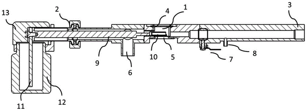
[0015] Such as figure 1 As shown, this embodiment includes a vacuum chamber 1 , one end of the vacuum chamber 1 is provided with an anti-pollution system adapter interface 2 , and the other end is provided with an electron microscope sample rod adapter interface 3 . An upper optical window 4 and a lower optical window 5 are arranged opposite to each other on the upper and lower walls of the vacuum chamber 1, and the upper and lower optical windows 4, 5 can be connected to the vacuum chamber 1 by bolts for easy disassembly. A vacuum system adapter interface 6 is provided on one side of the vacuum chamber 1 , which is used for connecting to a vacuum pump group for pumping vacuum for the vacuum chamber 1 . A vacuum valve 7 is arranged in the vacuum chamber 1 between the electron microscope sample rod adapter interface 3 and the upper and lower optical windows 4, 5, and a pre-vacuum is formed between the vacuum valve 7 and the electron microscope sample rod adapter interface 3 On...

Embodiment 2

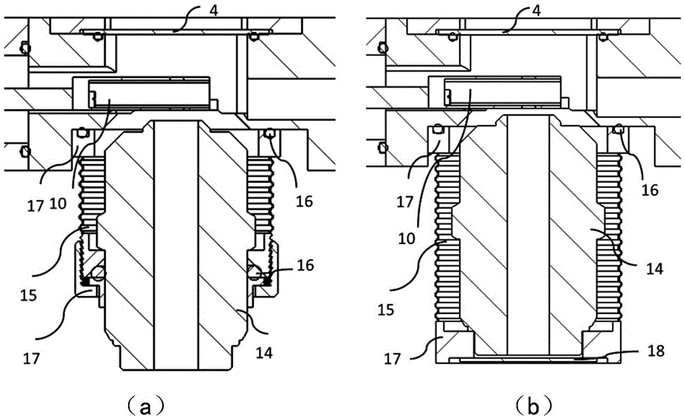
[0024] Such as figure 1 As shown, on the basis of Embodiment 1, this embodiment also includes an anti-pollution system. The anti-pollution system includes a heat-conducting rod 9 that partially extends into the vacuum chamber 1 through the anti-pollution system adapter interface 2. The heat-conducting rod 9 is located at One end in the vacuum chamber 1 is connected to a metal cold box 10, the metal cold box 10 is opposite to the upper and lower optical windows 4, 5, and a pair of light-through holes are oppositely arranged on the upper and lower surfaces of the metal cold box 10 (in the figure not shown). One end of the heat conducting rod 9 outside the vacuum chamber 1 is connected to a heat conducting core 11 . The anti-pollution system also includes a Dewar tank 12. A liquid nitrogen chamber is formed inside the Dewar tank 12. The liquid nitrogen chamber is filled with liquid nitrogen and the tank mouth is covered by a liquid nitrogen chamber cover 13. The heat conduction ...


PUM


Abstract

An optical vacuum cryostage for correlative light and electron microscopy comprises a vacuum chamber, an anti-contamination system adapter interface, an electron microscope specimen holder adapter interface, an upper optical window, a lower optical window, a vacuum pumping system adapter interface and a vacuum valve, wherein the anti-contamination system adapter interface is arranged in one end of the vacuum chamber, the electron microscope specimen holder adapter interface is arranged in the other end of the vacuum chamber, the upper optical window is arranged on the upper wall of the vacuum chamber, the lower optical window is arranged on the lower wall of the vacuum chamber and opposite to the upper optical window.

Description

technical field [0001] The invention belongs to the technical field of optical imaging, and in particular relates to an optical vacuum cooling table for associated imaging with an optical microscope and an electron microscope. Background technique [0002] The three-dimensional reconstruction technology of cryo-electron microscopy, X-ray crystallography, and nuclear magnetic resonance spectroscopy have become the most important experimental methods for high-resolution structural biology research, and more and more structures of biological macromolecules have been resolved one after another. However, people's ultimate goal is to analyze the structure of biological macromolecules and molecular machines in situ, so as to explain the essence of life activities at different levels such as molecules, organelles, and cells. [0003] In recent years, through the integration of fluorescent protein labeling technology, fluorescence microscopy, immuno-electron microscopy and cryo-elect...

Claims


Application Information

Patent Timeline
Patent Type & Authority Patents(China)
IPC IPC(8): G01N21/01G01N23/04G02B21/00H01J37/26
CPCG02B21/26G02B21/28H01J37/18H01J37/20H01J37/226H01J37/228H01J37/26H01J2237/182H01J2237/2001H01J2237/2002
Inventor 季刚李硕果孙飞
Owner INSITUTE OF BIOPHYSICS CHINESE ACADEMY OF SCIENCES
Why Eureka
Try Eureka