On-chip oscillator circuit capable of eliminating control logic delay

A technology for controlling logic and oscillators, applied in electrical pulse generator circuits, electrical components, generating electrical pulses, etc., can solve the problems of reducing temperature coefficient, affecting reliability, inconsistent clock frequency voltage coefficient and temperature coefficient, etc. Reduced voltage coefficient and temperature coefficient, simple circuit structure, and low cost

Active Publication Date: 2014-11-12
CHIPSEA TECH SHENZHEN CO LTD
View PDF4 Cites 10 Cited by
  • Summary
  • Abstract
  • Description
  • Claims
  • Application Information

AI Technical Summary

Problems solved by technology

For example, use resistors with complementary temperature coefficients to form a resistor with a small temperature coefficient, so that the temperature coefficient of T=R*C+Tlogic will be greatly reduced; in terms of reducing the voltage coefficient, you can use a stabilized voltage source to supply power to the oscillator, etc. Obtaining a small voltage coefficient, but paying the price of area and power consumption, is not advisable in the pursuit of low cost and low energy consumption; these methods usually lack the consideration of Tlogic's non-ideal factors; in fact, Tlogic is significantly affected by the power supply voltage and The influence of temperature changes, when the clock frequency becomes larger, such as >20MHz, because the proportion of Tlogic becomes larger, the influence will become more significant
Although Tlogic can be reduced as much as possible through design optimization, the extent of its reduction is limited by the process
On the other hand, if the clock signal frequency of the oscillator may be adjustable in multiple gears, the optimized configuration at a certain frequency, at another frequency, due to the change in the ratio of Tlogic / T, the influence of Tlogic will also change. , the result is that the voltage coefficient and temperature coefficient of the clock frequency of different gears are inconsistent, which affects the reliability

Method used


Image

  • On-chip oscillator circuit capable of eliminating control logic delay
  • On-chip oscillator circuit capable of eliminating control logic delay
  • On-chip oscillator circuit capable of eliminating control logic delay

Examples


Embodiment Construction

[0022] In order to make the object, technical solution and advantages of the present invention clearer, the present invention will be further described in detail below in conjunction with the accompanying drawings and embodiments. It should be understood that the specific embodiments described here are only used to explain the present invention, not to limit the present invention.

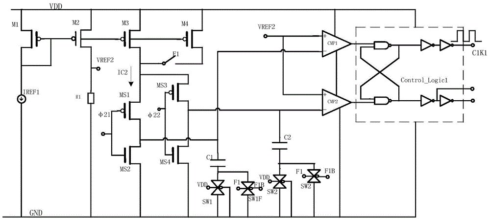
[0023] see figure 2 , shows the oscillator circuit that eliminates the control logic delay implemented by the present invention, wherein the reference current IREF1 is mapped through the current mirror M1 to M2, flows through R1 to generate the first reference voltage VREF2, and the second reference voltage is the reference ground, The current mirror M3 generates the first charge and discharge current IC2, one of the first charge and discharge switch groups is composed of PMOS switch MS1+NMOS switch MS2, the upper end of the first charge and discharge switch group is connected to the drain of the ...


PUM


Abstract

The invention discloses an on-chip oscillator circuit capable of eliminating control logic delay. The on-chip oscillator circuit mainly comprises a first reference voltage, a second reference voltage, a first charging and discharging current, a first charging and discharging switching group, a first charging and discharging capacitor, a first comparator and a control logic part, wherein the branch of the first charging and discharging capacitor is connected with a first switch tube in series, the first switch tube is in the open state, and the voltage of a starting signal and a power voltage are in positive correlation. According to the on-chip oscillator circuit capable of eliminating control logic delay, influences caused by control logic delay to a clock frequency voltage coefficient and a temperature coefficient can be eliminated, the circuit is especially suitable for the occasion with high clock frequency and big changes of a clock frequency range, the implementation cost is low, and the circuit is simple in structure and easy to implement.

Description

technical field [0001] The invention belongs to oscillators, in particular to a delay circuit for oscillators. Background technique [0002] The oscillator (OSC) circuit is used to provide a clock signal on the chip. For example, the oscillator used on a single-chip microcomputer provides a 12MHz clock signal, usually using an RC oscillator structure. The specific circuit diagram is shown in the attached figure 1 shown. It is a typical on-chip oscillator structure. The oscillator adopts a single comparator structure, in which the charging circuit IC0 charges the upper plate of the capacitor C0, φ1 is high, VREF0 is connected to the positive end of the comparator CMP; the upper plate of C0 is connected to the negative end of the comparator, and the lower plate is grounded; when When the voltage on the upper plate of C0 exceeds VREF0, the control logic makes φ1 low and φ2 high, so that the discharge current discharges C0, and VREF1 replaces VREF0 and connects to the positive...

Claims


Application Information

Patent Timeline
Patent Type & Authority Applications(China)
IPC IPC(8): H03K3/011H03K3/02
Inventor 李晓
Owner CHIPSEA TECH SHENZHEN CO LTD
Why Eureka
Try Eureka