
Combustor reducing emission of nitrogen oxide, gas boiler and control method

A burner and combustion chamber technology, which is applied in the field of gas-fired boilers and control and burners for reducing nitrogen oxide emissions, can solve the problems of increased cost, complex structure and control system, limited nitrogen oxide potential, etc., to reduce the peak flame Temperature, simple structure, and the effect of reducing nitrogen oxide emissions

Inactive Publication Date: 2014-11-26
INST OF ENGINEERING THERMOPHYSICS - CHINESE ACAD OF SCI
View PDF7 Cites 2 Cited by
  • Summary
  • Abstract
  • Description
  • Claims
  • Application Information

AI Technical Summary

Problems solved by technology

At present, research on low-nitrogen burners has been carried out in China, including multiple methods such as staged combustion, flue gas external circulation combustion, and normal-temperature air flameless combustion with agitator. Issues such as limited oxide potential

Method used


Image

  • Combustor reducing emission of nitrogen oxide, gas boiler and control method
  • Combustor reducing emission of nitrogen oxide, gas boiler and control method
  • Combustor reducing emission of nitrogen oxide, gas boiler and control method

Examples


no. 1 example

[0047] In an exemplary embodiment of the present invention, a burner that reduces emissions of nitrogen oxides is provided. The burner is suitable for 1t / h gas boiler with natural gas as fuel.

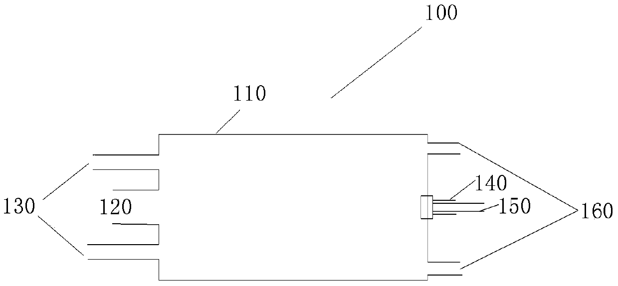
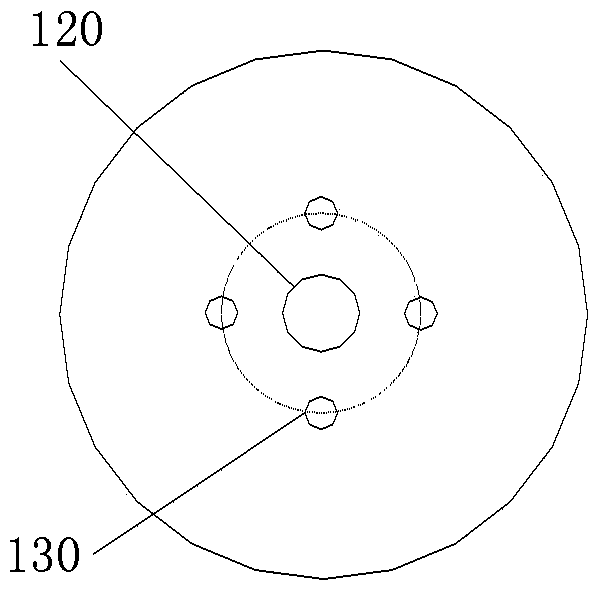
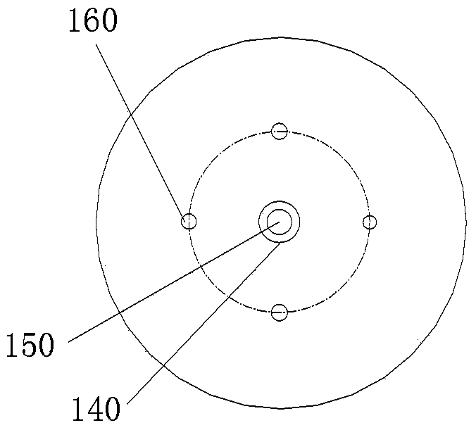
[0048] figure 1 It is a structural schematic diagram of a burner for reducing emissions of nitrogen oxides according to an embodiment of the present invention. Figure 2A and Figure 2B respectively figure 1 Left and right views of the burner shown. Such as figure 1 , Figure 2A and Figure 2B As shown, the burner 100 for reducing nitrogen oxide emissions in this embodiment includes:

[0049] The burner body 110 is a cylindrical combustion chamber surrounded by its front wall, cylindrical radiation wall and rear wall;

[0050] The flue gas outlet channel 120 is arranged at the center of the front wall of the burner body 110 and communicates with the combustion chamber;

[0051] Four main air nozzles 130 are arranged on the front wall of the burner body 110, and the radial peri...

no. 3 example

[0079] In yet another embodiment of the present invention, a method for controlling the above-mentioned burner is also provided.

[0080] In the burner provided by the first embodiment, the main air supply line, the main fuel supply line, the auxiliary air supply line and the auxiliary fuel supply line are all controlled by electric shut-off valves.

[0081] Figure 7 for figure 1 Flowchart of the control method for the shown burner. Such as Figure 7 As shown, the control method of the burner includes:

[0082] Step A: Open the electric cut-off valves of the auxiliary fuel supply pipeline and the auxiliary air supply pipeline, feed 50% of the total fuel into the auxiliary fuel nozzle 150, feed 60% of the total air into the auxiliary air nozzle 140, and ignite and burn , to preheat the combustion chamber;

[0083] In order to ensure stable and soft combustion in the burner, the auxiliary air nozzles 140 and auxiliary fuel nozzles 150 are required to preheat the cylindrica...


PUM


Abstract

The invention provides a combustor reducing emission of nitrogen oxide, a gas boiler and a control method. According to the combustor, the distance L1 between each main fuel spray nozzle and the center axis of a combustion chamber is different from the distance L2 from each main air spray nozzle and the center axis of the combustion chamber, a backflow vortex structure is formed in the combustion chamber, high-temperature flue gas generated by high-speed air injection and combustion is made to flow back and mix with air, so that a high-temperature low-oxygen mixture is formed, then the mixture is quickly mixed with fuel to achieve soft combustion, the temperature of peak flame in the combustion process is effectively reduced, and accordingly the effect that emission of the nitrogen oxide is reduced by 50-80% than that in direction combustion is achieved.

Description

technical field [0001] The invention relates to the technical field of gas boilers, in particular to a burner for reducing nitrogen oxide emissions, a gas boiler and a control method. Background technique [0002] Natural gas is a kind of boiler fuel. Compared with coal and oil, the dust, sulfur dioxide and other pollutants produced during the combustion process are significantly reduced. Although the emission of nitrogen oxides is also reduced, the emission is still at the same order of magnitude. Nitrogen oxides include nitric oxide, nitrogen dioxide, nitrous oxide, etc., which are extremely harmful to the environment and are one of the main sources of acid rain and photochemical smog. Increasingly stringent environmental regulations require technology upgrades to reduce emissions of pollutants such as nitrogen oxides. The combustion technology used in traditional gas boiler equipment is based on flaming combustion. Although these technologies are relatively mature, the f...

Claims


Application Information

Patent Timeline
Patent Type & Authority Applications(China)
IPC IPC(8): F23D14/02F23D14/58F23D14/46F22B31/00
Inventor 邵卫卫熊燕胡玉婷黄明明张哲巅肖云汉
Owner INST OF ENGINEERING THERMOPHYSICS - CHINESE ACAD OF SCI
Learn More