Surface air cooler with wet films of composite structures

A composite structure, surface cooler technology, applied in the direction of evaporator/condenser, refrigerator, refrigeration components, etc., can solve the problems of capillary structure removal, rapid freezing, complex structure, etc., to achieve the effect of easy cleaning and maintenance

Active Publication Date: 2014-12-10
童军
View PDF4 Cites 9 Cited by
  • Summary
  • Abstract
  • Description
  • Claims
  • Application Information

AI Technical Summary

Problems solved by technology

But this way doesn't work reliably
[0017] To sum up, although there are many ways to utilize condensed water at present, there are still the following defects: or high cost, or poor reliability, or complex structure, or low effective utilization rate
[0020] First, the capillary structure is directly arranged on the surface of the metal cooling fin (fin). The large-area, wet capillary structure is in direct contact with the air, allowing the water to evaporate directly on the surface of the capillary structure. However, since the condenser is installed outdoors, the fan drives a large number of When the air blows to the surface of the capillary structure, the dust in the outdoor air will gradually adsorb on the surface of the wet capillary structure, which will easily block the heat dissipation channel, not only will not increase the heat dissipation effect but will seriously reduce the heat dissipation performance; and the porous capillary structure adsorption It is also difficult to clean off the fine dust, and it is difficult to maintain in actual use;
[0021] Second, because the surface of one side of the metal fin (fin) is basically covered with fibrous capillary structure, if there is a lack of water during use, it is like covering a layer of heat-insulating cotton on the high-temperature metal fin (fin) This will also greatly reduce the heat dissipation effect of the original fins (fins), and in severe cases, it will damage the air conditioner compressor;
[0022] Third, the capillary water-absorbing layer and the water tank are located under the heat dissipation fins (fins). The water in the water tank must permeate upward under the capillary force, which is bound to be affected by gravity. It is difficult for the water to reach the upper end of the capillary structure in a short time. , so it is necessary to add pre-wet water pipes, solenoid valves and other components, which complicates the structure and reduces the reliability of work; at the same time, the dirt formed after the outdoor dust absorbs water will flow to the sink below along the capillary water absorption layer. Will fill up the sink and disable the entire capillary system;
[0023] Fourth, since the capillary structure is directly arranged on the surface of the metal fin (fin), and the capillary structure is a loose fiber structure, which is different from the physical properties of the metal fin (fin), the strength of the contact and cooperation between the two will be affected by the long-term outdoor High temperature, high humidity, vibration, wind blowing, especially the test of high-pressure water cleaning, large-area capillary fibers are easily damaged, easily peeled off from metal fins (fins), and there is a fit gap, which will reduce the service life and heat dissipation effect;
[0024] Fifth, the patented design only considers how to control the water supply, and does not consider the calcium and magnesium ions in the water. Although the heat dissipation effect of the condenser can be enhanced in a short period of time, as long as it runs for several months, the high-temperature condenser fins ( Fins) will cause the calcium and magnesium ions in the water to form a large amount of hard scale on the surface of the capillary structure, which will gradually reduce the heat dissipation effect and be extremely difficult to clean; at the same time, in order to control the water supply of tap water, it has designed a complex control system , such as a water level sensor in the water tank, a water stop valve and a solenoid valve to control the water flow in the water inlet pipe, etc., resulting in reduced work reliability;
[0025] Sixth, although it can enhance the heat dissipation effect of the outdoor condenser of the air conditioner in summer when the air conditioner is cooling, it can be known from the refrigeration and heating principles of the air conditioner that the condenser located in the outdoor high-temperature heat dissipation in summer becomes less effective when heating in winter. Without a low-temperature heat-absorbing evaporator, the water vapor in the air will condense a large amount of condensed water on the low-temperature metal fins (fins), so the fins (fins) of conventional air conditioners are made of smooth surfaces to facilitate the rapid condensation of condensed water. At this time, if a large-area capillary fiber structure is set on a smooth fin (fin), on the one hand, it will reduce the speed at which condensed water leaves the metal fin (fin), on the other hand, the capillary structure that absorbs condensed water will Seriously hinder the heat transfer between the air and the metal fins (fins), causing the condensed water to freeze rapidly, gradually forming a large area of ​​ice between the fins (fins), blocking the flow of air, forming a vicious circle, and making the air conditioner unable to operate normally; and At this time, it is impossible to remove the capillary structure from the fins (fins), and its practicability is not as good as the previous patent of directly spraying the fins. This is the fundamental reason why this patent cannot be practical.

Method used


Image

  • Surface air cooler with wet films of composite structures
  • Surface air cooler with wet films of composite structures
  • Surface air cooler with wet films of composite structures

Examples


Embodiment 1

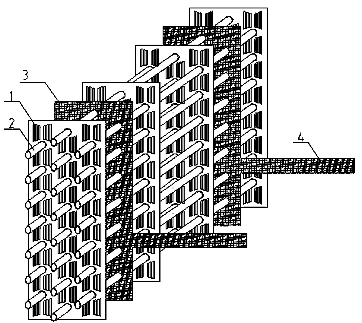
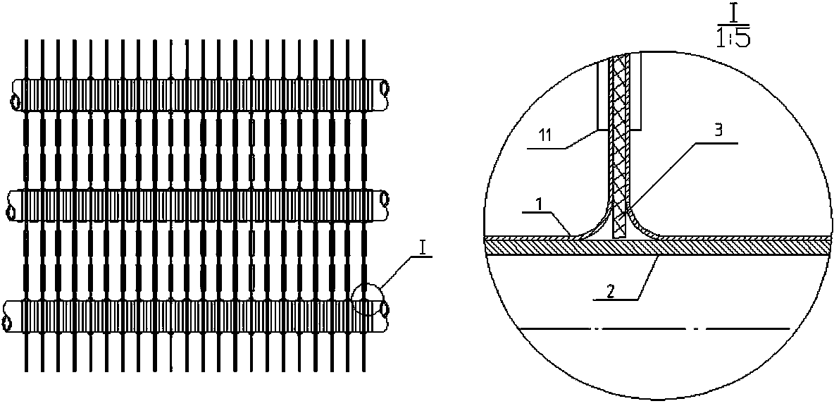
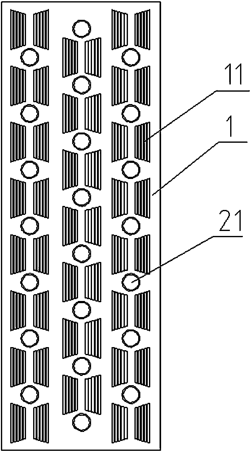
[0059] refer to figure 1 ,and figure 2 , the composite structure wet film surface cooler provided in this embodiment includes a plurality of fins 1 arranged in parallel at intervals and a plurality of heat exchange tubes 2 passing through the fins 1, and the heat exchange tubes 2 contain flowing refrigerant; A wet film layer 3 is pressed between the two fins 1 to form a "sandwich" structural unit; the dimensions of the wet film layer 3 are basically the same as those of the fins 1, so that the fins 1 are completely covered by the wet film layer 3 and in close contact , to ensure that water naturally, evenly and rapidly infiltrates to the entire surface of each fin 1 without any power.

[0060] refer to Figure 4 and Figure 5 , the water supply mode of the wet film layer 3 adopts the scheme of water-absorbing belt 4 plus water storage tank 5, and a water-absorbing belt 4 for introducing water into the wet film layer 3 extends outward from the middle and lower side of the ...

Embodiment 2

[0077] The difference from Example 1 is that the wet film layer 3 is uniformly distributed on one side of each fin 1 in strip shape, and the wet film layers 3 of all fins 1 can be arranged on the same side or on different sides.

Embodiment 3

[0079] The difference from Example 1 is that in some of the fins 1, a wet film layer 3 is pressed between two adjacent fins 1 to form a "sandwich" structure; in the other part of the fins 1, one part of each fin 1 The side is pressed with a wet film layer 3 .


PUM


Abstract

A wet-film surface air cooler of a composite structure comprises a plurality of fins and a plurality of heat-exchanging pipes, wherein the fins are arranged in parallel at intervals and the heat-exchanging pipes penetrate through the fins. A wet-film layer is arranged on the surfaces of the fins. At least one water absorption belt is extended outwards from the wet-film layer and is used for leading water into the wet-film layer. The wet-film surface air cooler of the composite structure is simple in structure, low in cost, free of power and high in reliability. On one hand, the heat-dissipation efficiency and the COP of condensate water or tap water applied to the surface air cooler of an air conditioner are improved, the air-discharging pressure is reduced when the air conditioner is used for cooling, the COP of a common air cooling air conditioner used for cooling is increased from 3.2 to 4.1, energy is saved by over 30%, and on the other hand, the surface air cooler of the air conditioner is prevented from being frosted in winter.

Description

technical field [0001] The invention relates to the technical field of air conditioning, in particular to a wet film surface cooler with a composite structure. Background technique [0002] The cooling mode of existing air conditioner is divided into air-cooled and water-cooled two kinds. [0003] The air-cooled air conditioner directly dissipates the heat generated during cooling to the air through the outdoor cooling coil and fan. The heat dissipation coil is usually called a surface air cooler (referred to as a surface cooler), and its structure is an array of multiple sets of copper tubes. Refrigerant flows inside the copper tubes, and dense heat dissipation aluminum fins are expanded outside the copper tubes. The air-cooled air conditioner can cool in summer and heat in winter, realizing one machine with two functions. When cooling in summer, when the surface cooler is used to dissipate heat, it is generally called a condenser; when heating in winter, when the surface...

Claims


Application Information

Patent Timeline
Patent Type & Authority Applications(China)
IPC IPC(8): F25B39/00F24F1/42
CPCF24F1/42F25B39/00
Inventor 童军
Owner 童军
Why Eureka
Try Eureka