Zero-sequence current suppression method of open type permanent magnet synchronous motor with double-inverter power supply
A technology of permanent magnet synchronous motor and open winding, which is applied in motor generator control, electronically commutated motor control, AC motor control, etc., to achieve high DC bus voltage utilization, wide motor speed operating range, and simple and reliable algorithms Effect
- Summary
- Abstract
- Description
- Claims
- Application Information
AI Technical Summary
Problems solved by technology
Method used
Image
Examples
specific Embodiment approach 1
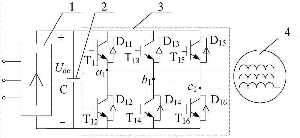
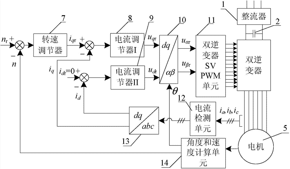
[0041] Specific implementation mode one: the following combination Figure 2 to Figure 8 Describe this embodiment, the zero-sequence current suppression method of the open-winding permanent magnet synchronous motor system powered by double inverters described in this embodiment, it is realized based on the open-type winding permanent magnet synchronous motor control system,
[0042] The motor control system includes a speed regulator 7, a current regulator I8, a current regulator II9, a dq-αβ coordinate transformation unit 10, a double inverter SVPWM unit 11, a current detection unit 12, an abc-dq coordinate transformation unit 13 and an angle with the speed calculation unit 14,
[0043] Its control method is: motor given speed n r After making a difference with the actual motor speed calculated by the angle and speed calculation unit 14, the given i of the q-axis current is generated by the speed regulator 7 qr , the given i of the q-axis current qr and the q-axis current ...
specific Embodiment approach 2
[0053] Specific implementation mode two: this implementation mode further explains implementation mode one, and the transformation formula of the abc-dq0 coordinate transformation unit 13-1 is:
[0054]
[0055] where i a is the current value of phase A at the motor input terminal, i b is the B-phase current value at the motor input terminal, i c is the C-phase current value of the motor input terminal.
specific Embodiment approach 3
[0056] Specific implementation mode three: the following combination Figure 2 to Figure 11 This embodiment will be described. This embodiment will further describe the first embodiment. The dual-inverter SVPWM unit 11 according to the α-axis voltage reference value u αr , β-axis voltage reference value u βr and the desired motor zero-sequence voltage reference value u 0r Generate 12 switching signals of the double inverter, so that the actual zero-sequence voltage u of the output of the double inverter 0 Approaching to the desired motor zero-sequence voltage reference value u 0r The specific implementation method is:
[0057] The dual inverters are inverter I3 and inverter II6, and the voltage vector U output by the dual inverters passes through the voltage vector U output by inverter I3 1 Subtract the voltage vector U of the inverter II6 output 2 get:
[0058] U=U 1 –U 2 ;
[0059] According to the triangular rule of vector synthesis, the spatial distribution diagra...
PUM
 Abstract
Description
Claims
Application Information
 - R&D
- Intellectual Property
- Life Sciences
- Materials
- Tech Scout
- Unparalleled Data Quality
- Higher Quality Content
- 60% Fewer Hallucinations
Browse by: Latest US Patents, China's latest patents, Technical Efficacy Thesaurus, Application Domain, Technology Topic, Popular Technical Reports.
© 2025 PatSnap. All rights reserved.Legal|Privacy policy|Modern Slavery Act Transparency Statement|Sitemap|About US| Contact US: help@patsnap.com


