Ceramic complex for light conversion and light-emitting device using same

A light-emitting device and light conversion technology, which is applied in the direction of light-emitting materials, electric solid-state devices, semiconductor devices, etc., can solve the problem of uneven light, and achieve the effects of excellent heat resistance, high output, and suppression of uneven light emission

Active Publication Date: 2014-12-24
UBE IND LTD
View PDF13 Cites 11 Cited by
  • Summary
  • Abstract
  • Description
  • Claims
  • Application Information

AI Technical Summary

Problems solved by technology

[0020] However, it has been found that the ceramic composite for light conversion obtained by the method described in Patent Document 4 has the following problem: Although the ratio of Gd or Ce is increased to adjust the fluorescence wavelength to, for example, 570 nm or more, it can maintain a high radiation beam, but in Light unevenness occurs in the light emission surface of the ceramic composite for light conversion

Method used


Image

  • Ceramic complex for light conversion and light-emitting device using same
  • Ceramic complex for light conversion and light-emitting device using same
  • Ceramic complex for light conversion and light-emitting device using same

Examples


Embodiment 1

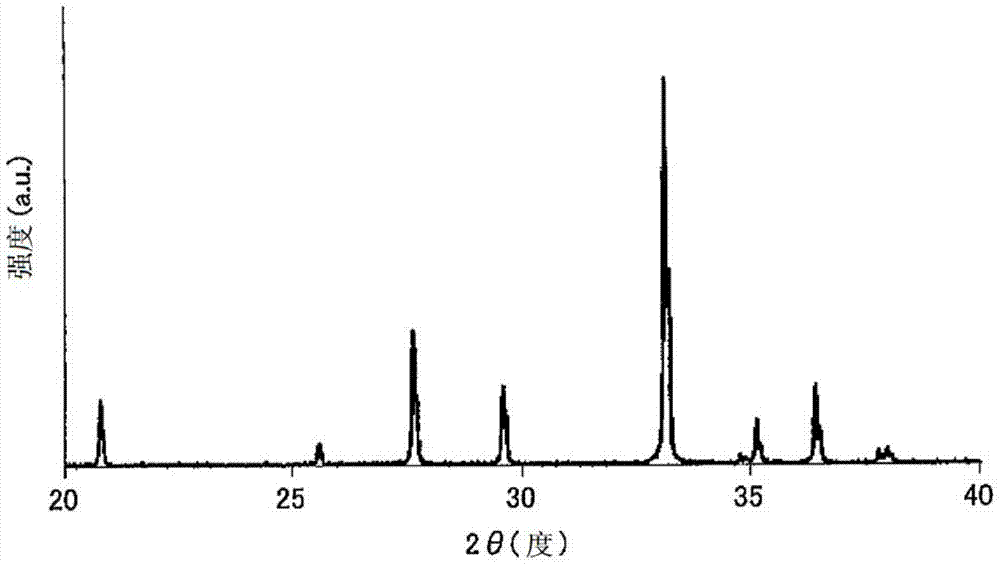
[0098] Weigh in AlO 3 / 2 Converted to 0.773 moles of α-Al 2 o 3 Powder (purity 99.99%), with TbO 7 / 4 Converted to 0.227×0.997 moles of Tb 4 o 7 Powder (purity 99.9%), 0.227 x 0.003 moles of CeO 2 Powder (purity 99.9%). After the powder was wet-mixed in ethanol by a ball mill for 16 hours, the ethanol was removed using an evaporator to obtain a raw material powder. The raw material powder is pre-melted in a vacuum furnace to obtain a unidirectionally solidified raw material.

[0099] Then, this raw material was directly put into a molybdenum crucible, and it was designed to be unidirectionally solidified by providing a melting holding zone in the upper part and a cooling zone in the lower part with a temperature gradient of 50°C / cm in the vertical direction (solidification direction). The melt holding area of ​​the device, at 1.33 x 10 -3 Pa(10 -5 The raw material is melted under the pressure of Torr). Then, under the same environment, the molybdenum crucible is lowere...

Embodiment 2

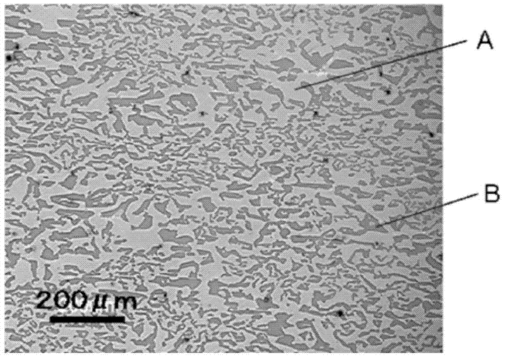
[0105] α-Al 2 o 3 Powder (purity 99.99%) with AlO 3 / 2 Converted to 0.773 mol, Tb 4 o 7 Powder (purity 99.9%) with TbO 7 / 4 Converted to 0.227×0.994 mol, CeO 2 The raw material was weighed so that the powder (purity: 99.9%) was 0.227×0.006 mol. A ceramic composite for light conversion of Example 2 was obtained in the same manner as in Example 1 except that the moving speed of the molybdenum crucible was 10 mm / hr. By the same method as in Example 1, it was confirmed that the photoconverting ceramic composite of Example 2 was made of Tb activated by Ce. 3 Al 5 o 12Phase and Al 2 o 3 constituted by phase. Table 1 shows the dominant fluorescence wavelength and relative fluorescence intensity of the obtained ceramic composite for light conversion.

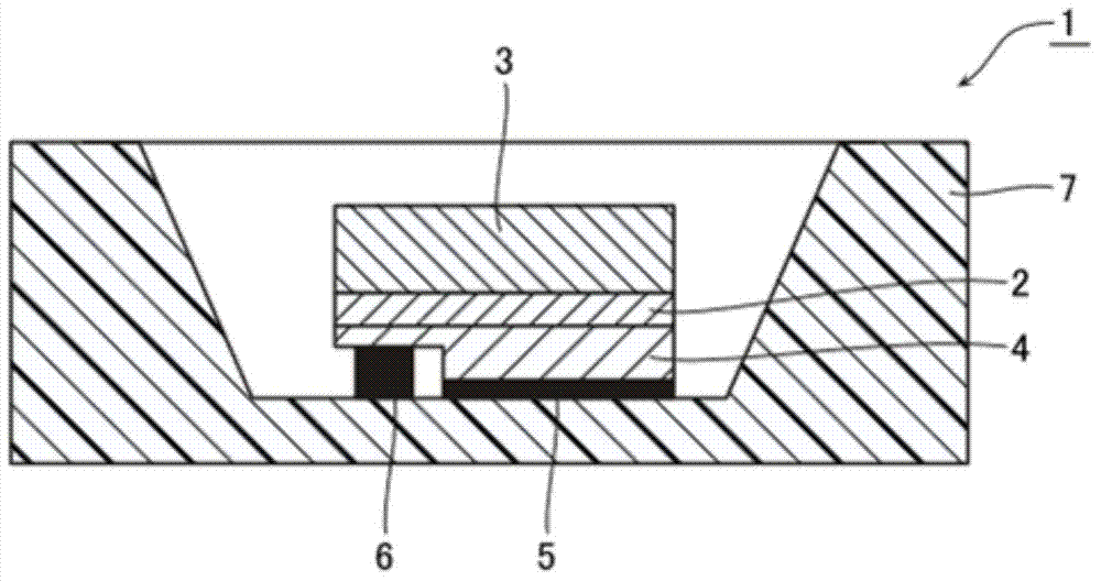
[0106] In addition, except that the thickness of the flat plate-shaped ceramic composite for light conversion was set to 0.14, 0.19, and 0.24 mm, a light-emitting device was produced for each thickness of the ceramic composite...

Embodiment 3

[0108] Weigh in AlO 3 / 2 Converted to 0.773 moles of α-Al 2 o 3 Powder (purity 99.99%), with TbO 7 / 4 Converted to 0.227×0.99 moles of Tb 4 o 7 Powder (purity 99.9%), 0.227×0.01 mol of CeO 2 Powder (purity 99.9%). A ceramic composite for light conversion was obtained by the same method as in Example 1 except that the moving speed of the molybdenum crucible was 10 mm / hr. By the same method as in Example 1, it was confirmed that the photoconverting ceramic composite of Example 3 was made of Tb activated by Ce. 3 Al 5 o 12 Phase and Al 2 o 3 constituted by phase. Table 1 shows the dominant fluorescence wavelength and relative fluorescence intensity of the obtained ceramic composite for light conversion.

[0109] In addition, except that the thickness of the flat plate-shaped ceramic composite for light conversion was set to 0.10, 0.15, and 0.19 mm to produce a light-emitting device, the same method as in Example 1 was used to determine the thickness of the flat plate sh...


PUM

PropertyMeasurementUnit
thicknessaaaaaaaaaa
thicknessaaaaaaaaaa

Abstract

Provided is a ceramic complex for light conversion that can lengthen a fluorescent dominant wavelength to 580 nm and can arbitrarily adjust the wavelength within a range of 570 to 580 nm, in which the fluorescent light intensity is not reduced even though the wavelength is lengthened, and that suppresses variation in light emittance. Further provided is a ceramic complex for light conversion with excellent heat resistance and suitable for increased output of a white-light-emitting device. Further provided is a light-emitting device that uses this ceramic complex for light conversion. The present invention is a ceramic complex for light conversion, which is a solidified material made from a composition expressed by formula (1) having an organization where at least two oxide phases, a first phase and a second phase, are continuously, three-dimensionally, and mutually entangled; wherein the first phase is a (Tb, Y)3Al5O12 phase activated by Ce that emits fluorescent light, and the second phase is an Al2O3 phase.

Description

technical field [0001] The present invention relates to a ceramic composite body for light conversion used in light-emitting devices such as light-emitting diodes that can be used in displays, lighting, and backlight sources. Background technique [0002] In recent years, research and development of white light-emitting devices using blue light-emitting elements as light-emitting sources has been extensively carried out. In particular, white light-emitting diodes using blue light-emitting diode elements are expected to rapidly increase in demand in the future because they are light in weight, do not use mercury, and have a long life. Furthermore, a light emitting device using a light emitting diode element as a light emitting element is called a light emitting diode (LED). As a method of converting blue light from a blue light-emitting diode element into white light, the most commonly performed method is to obtain a similar white color by mixing with yellow, which has a com...

Claims


Application Information

Patent Timeline
Patent Type & Authority Applications(China)
IPC IPC(8): C09K11/08C09K11/80H01L33/50
CPCH01L33/502C04B35/117C04B35/44C04B35/652C04B2235/3224C04B2235/3225C04B2235/3229C04B2235/764C04B2235/80H01L2224/16225C09K11/7774Y02B20/00
Inventor 射场久善石飞信一市薗泰之
Owner UBE IND LTD
Why Eureka
Try Eureka