
Endoscopic imaging probe and imaging method with same

An imaging probe and imaging technology, applied in the field of biomedical imaging, can solve the problems of difficulty in processing micropores, undetectable photoacoustic signals or low detection efficiency, and achieve the effect of easy processing and small diameter

Active Publication Date: 2015-01-07
白晓苓
View PDF8 Cites 16 Cited by
  • Summary
  • Abstract
  • Description
  • Claims
  • Application Information

AI Technical Summary

Problems solved by technology

[0005] However, in the prior art, U.S. Patent US20120271170 mentions that the optical fiber and the ultrasonic transducer are placed side by side so that the light beam overlaps with the ultrasonic receiving range to realize the reception of the photoacoustic signal; however, since the ultrasonic transducer itself has a certain size of emission and receiving aperture, this design leads to the photoacoustic signal excited outside the overlapping area cannot be detected or the detection efficiency is extremely low
However, US20080177183 mentions that the optical fiber is placed in a hollow transducer to realize that the laser excitation area overlaps with the ultrasonic receiving area, so that the ultrasonic detection of the entire excitation range can be realized; however, since the ultrasonic transducer is a piezoelectric material , it is difficult to process micro-holes in the middle of the transducer due to material characteristics

Method used


Image

  • Endoscopic imaging probe and imaging method with same
  • Endoscopic imaging probe and imaging method with same
  • Endoscopic imaging probe and imaging method with same

Examples


Embodiment 1

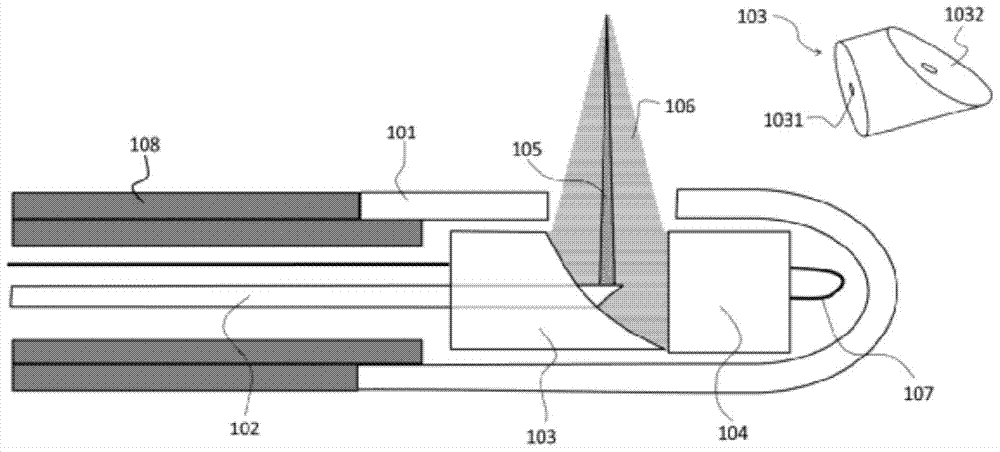
[0041] figure 1 It is a schematic structural diagram of an endoscopic imaging probe in this embodiment. Such as figure 1 As shown, the above-mentioned imaging probe includes an optical module 102, an ultrasound module, and a probe protective case 101 for accommodating the above-mentioned optical module 102 and the ultrasound module. Wherein, the ultrasound module includes an ultrasound reflection component and an ultrasound probe 104 , and in this embodiment, the ultrasound reflection component is an ultrasound reflection mirror. In addition, during normal use, the above-mentioned imaging probes are also respectively connected with the optical imaging module, the photoacoustic imaging module, the ultrasonic imaging module and the external control system, wherein the external control module has a function to control the optical imaging beam, the photoacoustic excitation beam and the ultrasonic beam. The function of emitting, collecting optical, photoacoustic, and ultrasonic s...

Embodiment 2

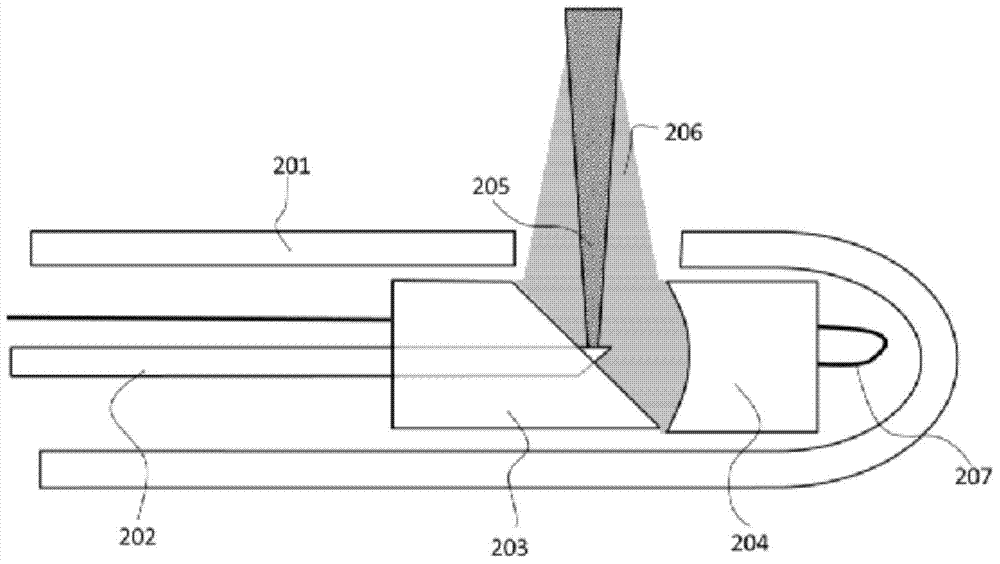
[0061] Such as figure 2 As shown, the difference between this embodiment and Embodiment 1 is that the optical imaging beam and the photoacoustic activation beam adopt divergent beams, while the ultrasonic probe 204 and the ultrasonic mirror 203 respectively adopt a focused ultrasonic probe and a planar ultrasonic mirror. Specifically, this embodiment is used for photoacoustic imaging, and in this embodiment, the photoacoustic excitation beam diverges to irradiate the tissue to excite the photoacoustic signal of the tissue, and then the converging ultrasonic detector 204 detects the one-dimensional photoacoustic signal.

[0062] The specific working principle and the connection relationship between components or modules are similar to those in Embodiment 1, and will not be repeated here.

Embodiment 3

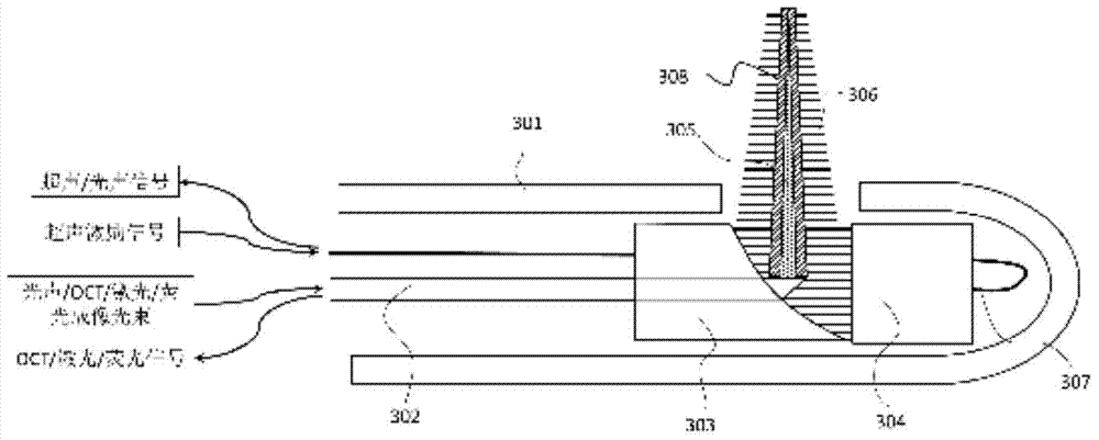
[0064] Such as image 3 As shown, this embodiment further exemplifies signal transmission on the basis of embodiment 1.

[0065] In this embodiment, the optical module 302 can be used to transmit various light beams, such as photoacoustic / OCT / laser / fluorescence imaging beams, and can also be used to collect various optical signals, such as OCT / laser / fluorescence signals. In addition, in this embodiment, the ultrasonic wire 307 can also be used to receive ultrasonic / photoacoustic signals in addition to transmitting ultrasonic excitation signals. The optical imaging light beam and the photoacoustic excitation light beam can be light beams with different focusing degrees. For example, in OCT imaging, a well-focused light beam is used to achieve high-resolution imaging, while in fluorescence imaging or photoacoustic imaging, the optical imaging used Excitation with a beam of light or photoacoustics can be a weakly focused beam to obtain a stronger corresponding excitation signal....


PUM


Abstract

The invention provides an endoscopic imaging probe. The endoscopic imaging probe comprises an optical module, an ultrasonic module and a probe protective shell, wherein the ultrasonic module comprises an ultrasonic reflecting module and an ultrasonic detector; the protective shell is provided with an imaging window; the ultrasonic reflecting module comprises an ultrasonic reflecting surface corresponding to the imaging window in position and is arranged on the optical path of optical imaging light beams and / or optoacoustic exciting light beams, so that the optical imaging light beams and / or the optoacoustic exciting light beams can be emitted out in a direction coaxial to the ultrasonic wave beams reflected through the ultrasonic reflecting surface after penetrating the ultrasonic reflecting module. Besides, the invention also provides an endoscopic imaging method with the endoscopic imaging probe. Therefore, single-mode or multi-mode imaging of the same position point through optoacoustic imaging, optical imaging and ultrasonic imaging can be achieved, the imaging accuracy of every mode can be improved, the detecting efficiency of entire one-dimensional optoacoustic signals can be improved, and the diameter of the probe and the probe machining difficulty can be reduced as much as possible.

Description

technical field [0001] The invention relates to biomedical imaging technology, in particular to an endoscopic imaging probe and an imaging method using the imaging probe. Background technique [0002] Endoscopic imaging, as a non-invasive imaging method, can effectively extend the human line of sight, and is widely used in image diagnosis and image-guided therapy in many fields such as the digestive tract, cardiovascular and cerebrovascular systems, urinary system, and respiratory tract, which greatly promotes the development of diseases. inspection accuracy. [0003] In recent years, multi-modal endoscopic imaging technologies have developed rapidly, such as ultrasound, OCT (optical coherence tomography) dual-mode endoscopic imaging technologies, and new photoacoustic endoscopic imaging technologies. Among them, ultrasound and OCT dual-mode endoscopic imaging technology can more accurately reflect the characteristics of biological tissues by combining the ultra-large imagi...

Claims


Application Information

Patent Timeline
Patent Type & Authority Applications(China)
IPC IPC(8): A61B1/00
CPCA61B1/00071A61B1/05A61B5/0095A61B8/12A61B8/5238
Inventor 白晓苓
Owner 白晓苓
Learn More