Magnetic suspension axial flow type spiral driving device

A screw drive, magnetic suspension shaft technology, applied to other medical devices, hypodermic injection devices, suction devices, etc., can solve the problems of easily destroying the liquid cell structure, low current consumption, complex structure, etc., to achieve flexible control, less power loss, Small size effect

Active Publication Date: 2015-01-07
SHANDONG UNIV OF SCI & TECH
View PDF9 Cites 9 Cited by
  • Summary
  • Abstract
  • Description
  • Claims
  • Application Information

AI Technical Summary

Problems solved by technology

[0003] At present, the magnetic levitation axial flow heart assist device mostly adopts the hybrid magnetic levitation structure, which relies on the force between the permanent magnets to establish the initial working state, realizes the axial and radial non-contact levitation, and then dynamically adjusts the levitation position of the rotor through the electromagnetic force. To achieve stable suspension, the system consumes less current, but the volume is too large, and the structure needs to be further optimized
The magnetic levitation rotor needs to use the leading impeller and the rear guiding impeller to realize the axial drive of the liquid. The structure is complex, which is not conducive to reducing the volume, and the impeller is easy to damage the liquid cell structure in the state of rapid rotation.

Method used


Image

  • Magnetic suspension axial flow type spiral driving device
  • Magnetic suspension axial flow type spiral driving device

Examples


Embodiment

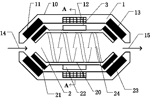
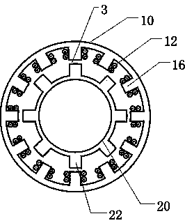
[0014] Embodiment: A magnetic levitation axial-flow screw driving device.

[0015] The axial force on the rotor 2 includes: the axial rightward repulsion of the left axially magnetized permanent magnet 11 of the stator to the left axially magnetized permanent magnet 21 of the rotor, and the right axially magnetized permanent magnet 13 of the stator to the right axial magnetization of the rotor The axial leftward repulsion of the permanent magnet 23, the axial component of the buoyancy force on the rotor 2, the axial component of the gravity on the rotor 2 and the axial reaction force on the rotor 2 when driving the water flow, the resultant force of these five axial forces The axial non-contact suspension of the rotor 2 is realized.

[0016] The radial force on the rotor 2 includes: the radial repulsion force of the left axially magnetized permanent magnet 11 of the stator to the left axially magnetized permanent magnet 21 of the rotor, and the right axially magnetized permane...


PUM


Abstract

The invention relates to the field of artificial heart assisting devices, and in particular relates to a magnetic suspension axial flow type spiral driving device. The device comprises three parts, namely, a stator (1), a rotor (2) and a clearance (3); a winding coil (12) is arranged in the middle of an inner cavity of a stator housing (10); a stator left axial magnetizing permanent magnet (11) is arranged at the left side of the inner cavity of the stator housing (10), and while a stator right axial magnetizing permanent magnet (13) is arranged at the right side of the inner cavity of the stator housing (10); a liquid inlet (14) is arranged in the axial left side of the stator (1), and while a liquid outlet (15) is arranged in the axial right side of the stator (1); the rotor housing (20) is in a shape of a circular barrel of which the two ends are opened, wherein the rotor housing (20) is that a spiral driving sheet (24) is arranged at the inner part, a rotor iron core (22) is arranged in the middle of the outer wall, a rotor left axial magnetizing permanent magnet (21) is arranged at the left side of the outer wall, and a rotor right axial magnetizing permanent magnet (23) is arranged at the right side of the outer wall. The magnetic suspension axial flow type spiral driving device is simple and compact in structure, small in size, high in stability, and can be implanted into a human body for long-term use.

Description

technical field [0001] The invention relates to an artificial heart assisting device, in particular to a magnetic suspension axial-flow screw driving device. Background technique [0002] Cardiac assist devices use biomechanical means to partially or completely replace the pumping function of the heart to maintain blood circulation throughout the body. At first, it was mainly based on bionic design and simulated heart beat, and gradually developed to focus on magnetic levitation control technology. The magnetic levitation heart assist device can realize the non-contact operation of the rotor, eliminate mechanical friction and wear, and solve the problems of severe heat generation, easy wear, great damage to blood cells, and easy formation of hemolysis and thrombus at the bearing of the mechanical heart assist device. The application of cardiac assist devices to the human body becomes possible. Magnetically levitated cardiac assist devices are divided into axial flow and cen...

Claims


Application Information

Patent Timeline
Patent Type & Authority Applications(China)
IPC IPC(8): A61M1/12
CPCA61M2210/125A61M60/148A61M60/40A61M60/50
Inventor 孙传余李波肖林京文艺成
Owner SHANDONG UNIV OF SCI & TECH
Why Eureka
Try Eureka