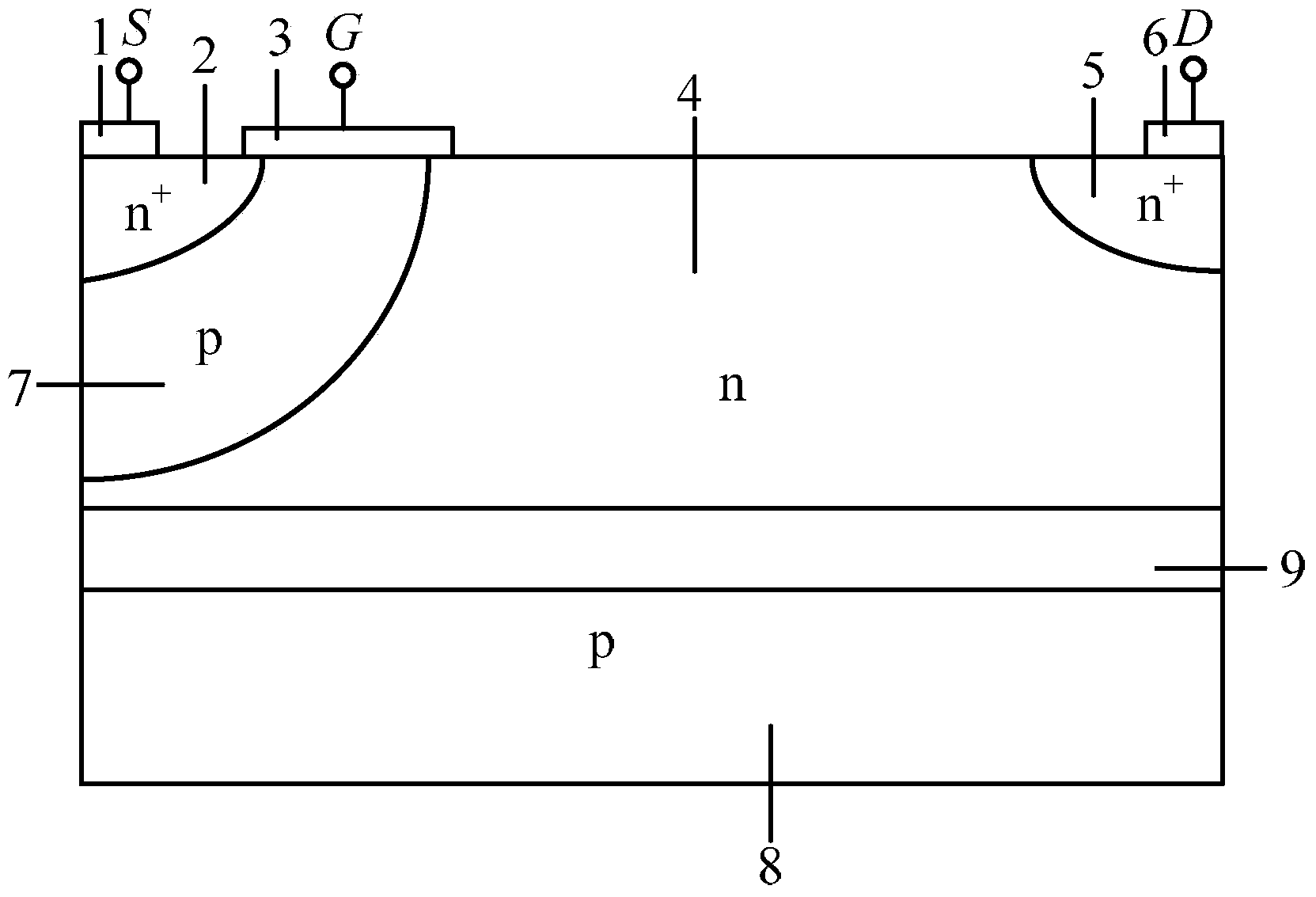
Linear space distribution fixed charge island SOI withstand voltage structure and power device
A fixed charge island and fixed charge technology, applied in the direction of transistors, etc., can solve the problem of the difficulty of realizing the thin silicon layer of the charge island, and achieve the effect of enhancing the withstand voltage, improving the vertical withstand voltage, and alleviating the self-heating effect.
- Summary
- Abstract
- Description
- Claims
- Application Information
AI Technical Summary
Problems solved by technology
Method used
Image
Examples
Embodiment 1
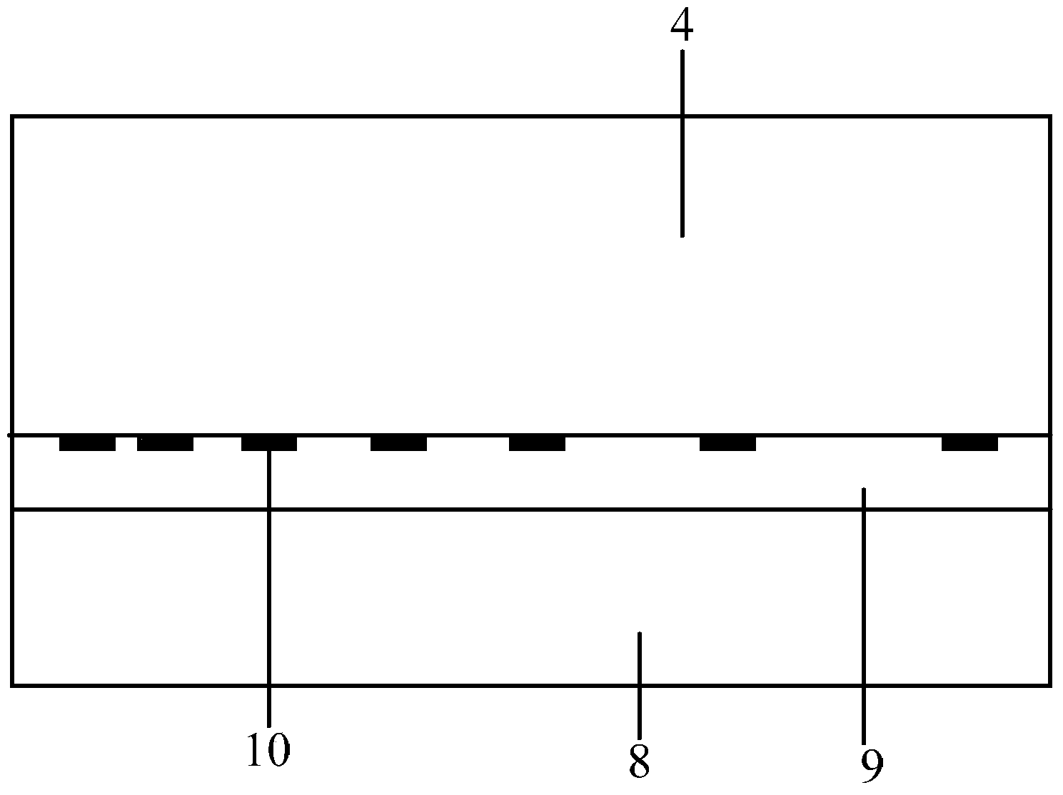
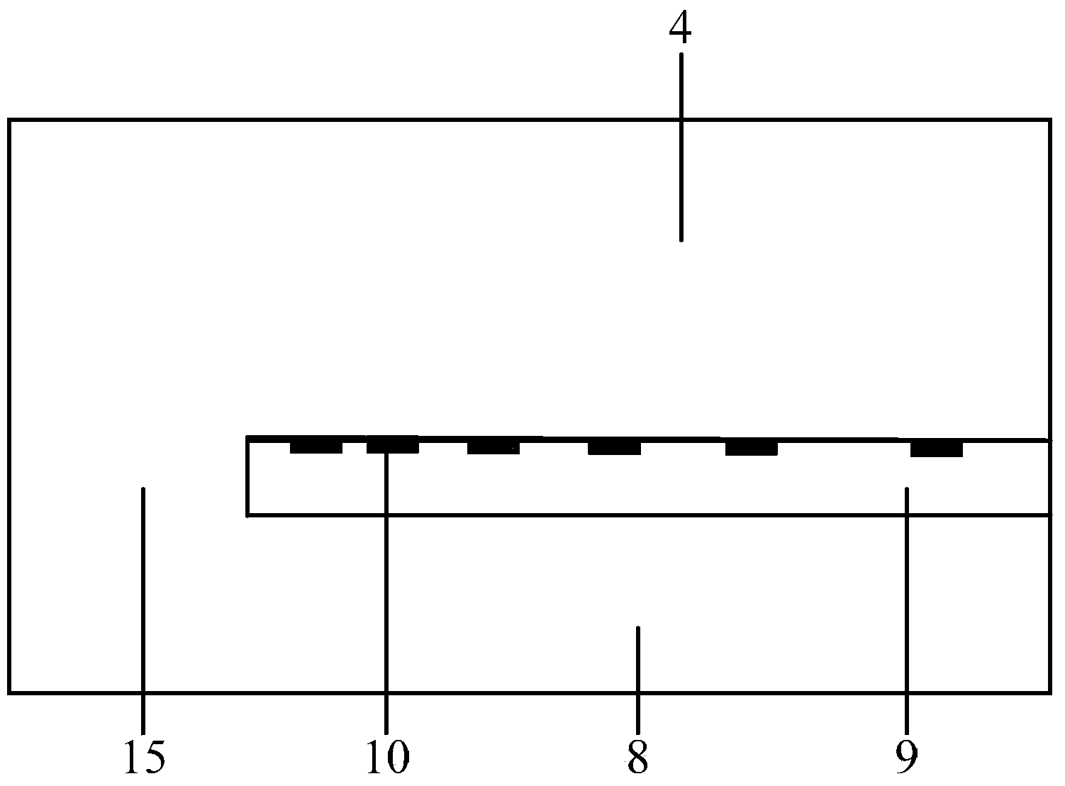
[0034] A linear space distribution fixed charge island SOI withstand voltage structure, such as figure 2 As shown, the withstand voltage structure at least includes a substrate layer 8, a buried dielectric layer 9 and an active layer 4, and the substrate layer 8, buried dielectric layer 9 and active layer 4 are stacked in sequence from bottom to top. The structures of the substrate layer 8 , the dielectric buried layer 9 and the active layer 4 are the same as or similar to the basic structures of existing power devices in the prior art. The material of the active layer 4 can be Si, SiC, GaAs, SiGe, GaN or other semiconductor materials. The material of the dielectric buried layer 9 can be SiO 2 Or a low-k material, where the low-k material (low dielectric constant) can be carbon doped oxide or SiOF. However, the material of the active layer 4 and the material of the buried dielectric layer 9 are not limited to the materials listed above. The above-mentioned buried dielectri...
Embodiment 2
[0039] An SOI power device with a fixed charge island SOI withstand voltage structure distributed in linear intervals, that is, a SOILDMOS device, such as Figure 4 As shown, it includes a substrate layer 8, a dielectric buried layer 9 and an active layer 4 stacked sequentially from bottom to top. An active region 2 , a channel region 7 and a drain region 5 are arranged at upper corners on both sides of the active layer 4 . The source region 2 and the channel region 7 are adjacent to each other, and are arranged at the upper corner of one side of the active layer 4 at the same time. The drain region 5 is disposed at the upper corner of the other side of the active layer 4 . The surface of the active layer 4 is provided with a source 1 , a gate 3 and a drain 6 . The source electrode 1 overlies the source region 2 , and the gate 3 overlies both the source region 2 and the channel region 7 . The drain 6 overlies the drain region 5 . A plurality of high-concentration fixed cha...
Embodiment 3
[0043] Another SOI power device with linear pitch distribution fixed charge island SOI withstand voltage structure, that is, SOI IGBT device, such as Figure 7 As shown, it includes a substrate layer 8, a dielectric buried layer 9 and an active layer 4 stacked sequentially from bottom to top. A cathode charge region 12 , a channel region 7 and an anode charge region 13 are provided at upper corners on both sides of the active layer 4 . The cathode charge region 12 is in contact with the channel region 7 and is also arranged at the upper corner of one side of the active layer 4 . The anode charge region 13 is disposed at the upper corner of the other side of the active layer 4 . The surface of the active layer 4 is provided with a cathode 11 , a grid 3 and an anode 14 . The cathode 11 overlies the cathode charge region 12 , and the gate 3 overlies both the cathode charge region 12 and the channel region 7 . The anode 14 overlies the anode charge region 13 . A plurality of h...
PUM
 Abstract
Description
Claims
Application Information
 - R&D
- Intellectual Property
- Life Sciences
- Materials
- Tech Scout
- Unparalleled Data Quality
- Higher Quality Content
- 60% Fewer Hallucinations
Browse by: Latest US Patents, China's latest patents, Technical Efficacy Thesaurus, Application Domain, Technology Topic, Popular Technical Reports.
© 2025 PatSnap. All rights reserved.Legal|Privacy policy|Modern Slavery Act Transparency Statement|Sitemap|About US| Contact US: help@patsnap.com


