
Heterodyne interferometer vibration measurer based on laser doppler effect

A technology of Doppler effect and heterodyne interference, which is applied in the field of heterodyne interferometric vibrometers, can solve the problem that optical devices cannot be placed in an aligned state, and achieve the effect of avoiding internal structural differences and improving vibration measurement accuracy.

Inactive Publication Date: 2015-01-28
SICHUAN UNIV
View PDF5 Cites 26 Cited by
  • Summary
  • Abstract
  • Description
  • Claims
  • Application Information

AI Technical Summary

Problems solved by technology

Due to the mixing of frequency and polarization state of the light beam in the optical path of the heterodyne interferometric phase vibrometer, and the placement of the optical components cannot achieve the ideal alignment state, there will still be a large error

Method used


Image

  • Heterodyne interferometer vibration measurer based on laser doppler effect
  • Heterodyne interferometer vibration measurer based on laser doppler effect
  • Heterodyne interferometer vibration measurer based on laser doppler effect

Examples


Embodiment 1

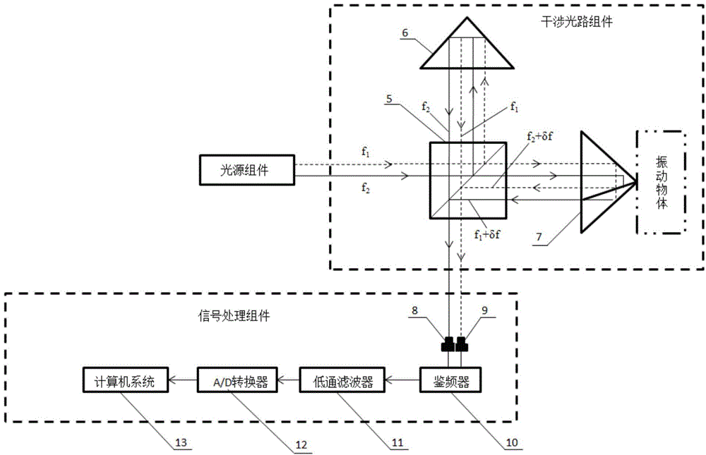
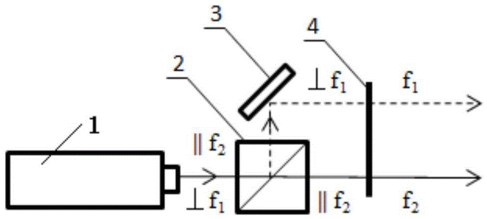
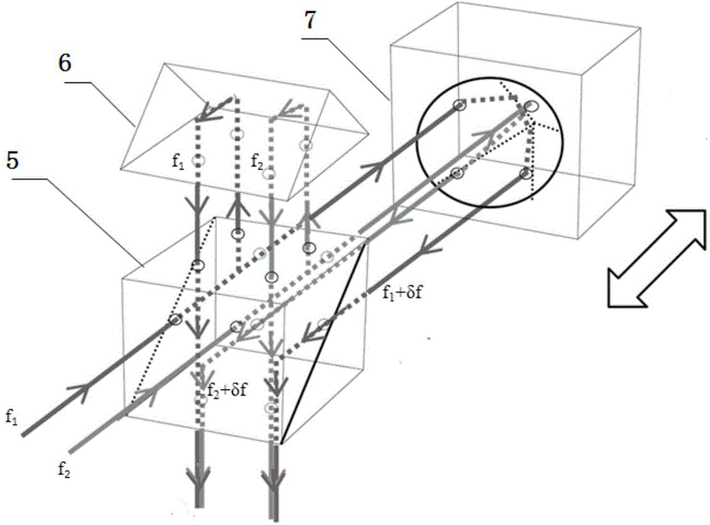
[0033] In this embodiment, the structural schematic diagram of the heterodyne interferometric vibrometer based on the laser Doppler effect is as follows figure 1 , 2 , 3, including light source components, interference optical path components and signal processing components.

[0034] The light source component is composed of a dual-frequency laser source 1, a polarization beam splitter 2, a reflector 3 and a polarizer 4. The dual-frequency laser source 1 is a transverse Zeeman dual-frequency laser with a frequency difference of 60 MHz, and the emission wavelength is 633 nm. The polarization beam splitter prism 2 is ZF optical glass coated with polarized beam splitting film on the inclined surface, and the four outer surfaces are coated with narrow-band multi-layer anti-reflection film. The applicable wavelength is 633nm. glass), the applicable wavelength is 633nm, and the polarizer 4 is a linear polarizer made of a dichroic material. The structure of the light source assemb...

Embodiment 2

[0038] In this embodiment, the laser Doppler effect-based heterodyne interferometric vibrometer described in Embodiment 1 is used for analog vibration measurement. The measurement method is as follows:

[0039] 1. With the audio equipment as the vibration source, the curved prism 7 in the heterodyne interferometric vibrometer described in Embodiment 1 is fixed in a box, the box is fixed in front of the speaker of the audio equipment and close to the speaker, and the audio equipment The vibration frequency is adjusted to 23Hz.

[0040] 2. Turn on the dual-frequency laser light source 1 in the heterodyne interferometric vibrometer described in Embodiment 1 and make the signal processing components work.

[0041] See the measurement results Figure 5 .

[0042] Comparative Test

[0043] The simulated vibration measurement is performed by using the high-precision dual-frequency simultaneous measurement laser heterodyne interference phase vibrometer optical path disclosed in t...


PUM


Abstract

Disclosed is a heterodyne interferometer vibration measurer based on a laser doppler effect. The heterodyne interferometer vibration measurer based on the laser doppler effect comprises a light source component, an interference light path component and a signal processing component. The light source component comprises a double frequency laser light source, a polarization splitting prism, a reflecting mirror and a polarizer; the interference light path component comprises an unpolarized splitting prism, a rectangular prism and a curved-surface prism which is mounted on a to-be-measured vibration object; the signal processing component is used for receiving two beams of interference light that is emitted by the unpolarized splitting prism in the interference light path component, an interference light signal is converted to an electric signal to be processed, and vibration information of the to-be-measured vibration object is obtained. By means of the heterodyne interferometer vibration measurer based on the laser doppler effect, the vibration measuring accuracy can be improved.

Description

technical field [0001] The invention belongs to the technical field of laser interference vibrometer, in particular to a heterodyne interferometric vibrometer based on the laser Doppler effect. Background technique [0002] With the rapid development of modern engineering technology, especially the development of aviation, aerospace, ocean engineering, machinery manufacturing and other technologies, it is necessary to measure vibration with high precision to collect vibration signals and process the response data during operation in real time, so as to Vibration and noise analysis of mechanical structural systems. Vibration measurement commonly used electrostatic capacitance, eddy current, laser triangulation, piezoelectric and laser Doppler methods. Laser Doppler vibration measurement technology is a technology for high-precision vibration detection through laser interference. Compared with other methods, it has high precision, fast dynamic response, long measurement dista...

Claims


Application Information

Patent Timeline
Patent Type & Authority Applications(China)
IPC IPC(8): G01H9/00
Inventor 冯国英周晟阳周寿桓
Owner SICHUAN UNIV
Learn More