#CMT# # / CMT# Controlling a cooling of a material (4) using a
coolant, comprises controlling a supply (13) of the
coolant to the material by at least one
actuator (6) which can be set to at least two different positions, where an
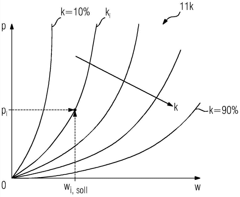
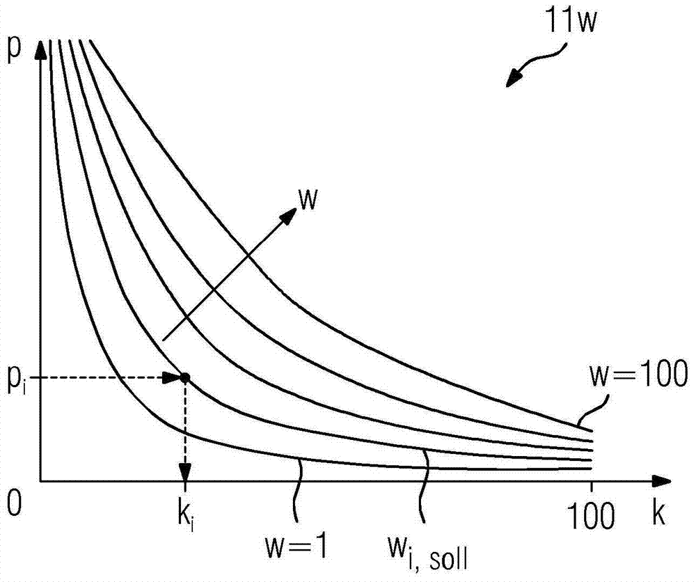
actuator curve set is assigned to the
actuator, which specifies a relationship between a
coolant stream, a pressure of the coolant, and a position of the actuator; adjusting a coolant
stream; determining a corresponding position of the target coolant
stream and adjusting the actuator in the determined position. #CMT# : # / CMT# Controlling a cooling of a material (4) using a coolant, comprises controlling a supply (13) of the coolant to the material by at least one actuator (6) which can be set to at least two different positions, where an actuator curve set is assigned to the actuator, which specifies a relationship between a coolant stream, a pressure of the coolant, and a position of the actuator; adjusting a coolant stream, where the pressure of the coolant upstream of at least one actuator, when seen in the flow direction of the coolant, is determined from pressure value of the actuator curves to the determined; determining a corresponding position of the target coolant stream and adjusting the actuator in the determined position. Independent claims are also included for: (1) a
computer program product for controlling the cooling process of the material using the coolant, where the
computer program product, when executed by a computer unit, performs the steps comprising determining the pressure of the coolant upstream of at least one actuator, and a coolant stream corresponding position of the actuator curve, and generating a
signal which triggers adjustment of the actuator and sets actuator in the determined position; (2) a control device (7) for controlling a cooling
system of a material, comprising a storage unit which is designed for the storage of actuator curves, a processor unit which is adapted to determine position of the actuator, and a
signal unit, which is adapted to transmit a
signal to adjust at least one actuator in the determined position to a
control unit; and (3) a cooling section (2) of a
metal processing line, preferably a rolling line, comprising a control device for controlling the cooling of a material in the cooling section. #CMT#USE : # / CMT# The method is useful for controlling a cooling of a material using a coolant. #CMT#
ADVANTAGE : # / CMT# The method: utilizes simple switching valves, thus it is carried out in cost efficient manner; and allows rotation of pump without changing the supply pressure of the intensive cooling
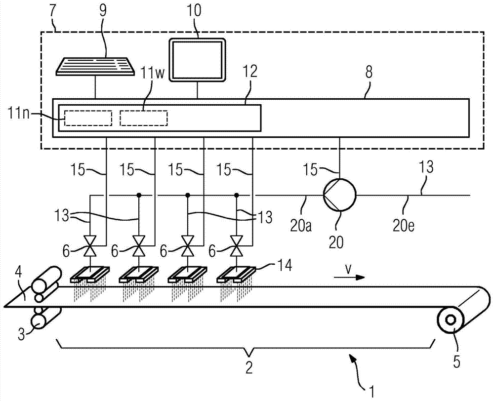
system. #CMT#DESCRIPTION OF DRAWINGS : # / CMT# The figure shows a
schematic representation of controlling a coolant stream. 2 : Cooling section 4 : Material 6 :
Actuator 7 : Control device 13 : Supply #CMT#
INSTRUMENTATION AND TESTING : # / CMT# Preferred Components: At least one actuator, which can be set to at least two different positions, is continuously variable and is continuously adjusted in the determined position. At least one
coolant pump arranged in the flow direction of the coolant and upstream to at least one actuator, and a pump curve is assigned which specifies: a relationship between a rotational speed of the pump, a
pressure difference of the coolant that exists between a suction pressure at an input side of the pump and an output pressure at an output side of the pump; and a coolant stream. The coolant stream is adjusted and is determined from pressure value of the pump curves to the determined, and a corresponding rotational speed of the target coolant stream is determined and the pump is set to determined speed. The position of at least one actuator and the rotational speed is determined to operate at least one
coolant pump in
single step as a common set of reference values, where the pressure of the coolant prior to at least one actuator is same as the output pressure at the output side of the pump. The suction pressure is measured or estimated on the inlet side of the pump. The actuator curve is adapted to detect, preferably to measure the pressure of the coolant, by which the coolant stream of the coolant is determined, preferably measured, from which position of the actuator corresponding to the values to be determined, is determined from the actuator curve, where the position of the actuator determined from the actuator-curve is compared with a measured position of the actuator. The actuator curve is modified such that the position of the actuator determined from the actuator curve coincides with the measured position of the actuator. The position of the actuator is represented by function of the coolant stream and coolant pressure for the
adaptation of the actuator curve by means of
basis function of coolant stream and coolant pressure which is summation of amplification factors of
basis function of coolant stream and coolant pressure. The pump curve is determined by the
pressure difference and the coolant stream and pump speed is determined from the pump curve corresponding to the determined values, where the pump speed determined from the pump curve is compared with a measured pump speed, and the pump curve is modified such that the pump speed calculated from the pump curve coincides with the measured pump speed as measured by the pump rotational speed. The pump speed is represented by function of the coolant stream, and difference of outlet pressure and suction pressure for the
adaptation of the pump curve by means of
basis function of coolant stream, and difference of outlet pressure and suction pressure which is summation of amplification factors of basis function of coolant stream, and difference of outlet pressure and suction pressure. The control device comprising at least one actuator is designed as a valve or a control flap. At least one actuator is continuously adjustable. The cooling section includes intensive cooling section and / or a
laminar cooling section.

