High-power LED heat accumulating type solid-liquid phase change heat dissipation device

A solid-liquid phase change and heat dissipation device technology, applied in the field of lighting, can solve the problems of lowering the temperature of the LED package, lowering the temperature of the LED chip, and large volume changes of the liquid-gas phase change, so as to reduce cost and weight, and reduce dependence , good adjustment effect

Inactive Publication Date: 2015-02-11
GUANGDONG XIAN JIAOTONG UNIV ACADEMY
View PDF9 Cites 6 Cited by
  • Summary
  • Abstract
  • Description
  • Claims
  • Application Information

AI Technical Summary

Problems solved by technology

S.L.Lee et al. [S.L.Lee, Z.H.Yang, Y.Hsyua, Cooling of a heated surface by mist flow, Journal of Heat Transfer, 1994,116(1):167.] and patent CN2735548 by forced convection of air and silicon oil respectively Cooling to reduce the temperature of the LED chip, the disadvantage is that the active cooling system used requires additional energy consumption and poor reliability
Patent CN1828956A discloses a high-power LED heat dissipation package. Its principle is to use low boiling point liquid droplets to impact the heat dissipation device to reduce the temperature of the LED package body. The disadvantages are that the temperature of the temperature control surface is uneven, the pressure difference is large, and the cooling surface is easy. produce corrosion
Patent CN101315927A discloses a high-power LED phase-change cooling device. Its principle is to use the liquid-gas phase change of the working medium to realize the thermal isothermal effect of the heat sink body to reduce the temperature

Method used


Image

  • High-power LED heat accumulating type solid-liquid phase change heat dissipation device
  • High-power LED heat accumulating type solid-liquid phase change heat dissipation device
  • High-power LED heat accumulating type solid-liquid phase change heat dissipation device

Examples


Embodiment Construction

[0024] The present invention will be described in further detail below in conjunction with the accompanying drawings.

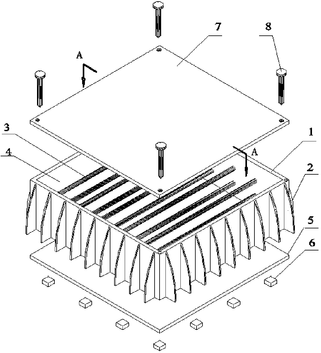
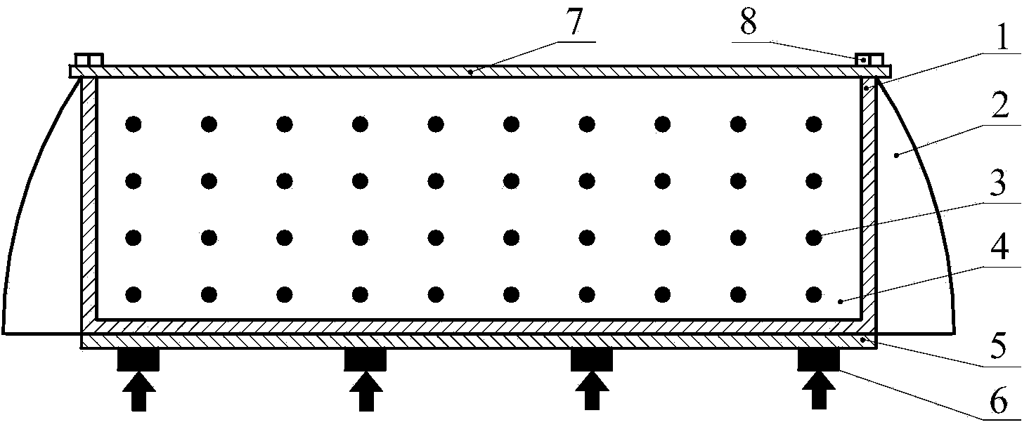
[0025] like figure 1 and figure 2 As shown, the present invention includes a heat sink cavity 1 whose bottom is used to connect with the LED package 6, and the bottom of the heat sink cavity 1 is provided with an expansion board 5 for fixing the LED package 6, and the material of the expansion board 5 is Metal with high thermal conductivity (such as aluminum or copper), one side of the expansion board 5 is connected to the bottom of the heat sink cavity 1 by welding or silicone grease with high thermal conductivity, and the other side of the expansion board 5 is connected to the LED package 6 through high thermal conductivity. Coefficient of silicone grease or welding closely connected, the LED package 6 adopts a single LED package or LED lamp array (circular array or rectangular array). The outer wall of the heat sink cavity 1 is fixed with a number of he...


PUM


Abstract

The invention discloses a high-power LED heat accumulating type solid-liquid phase change heat dissipation device which comprises a heat sink cavity, wherein the bottom of the heat sink cavity is used for being connected with an LED packaging part; a plurality of heat radiating fins are arranged on the outer side wall of the heat sink cavity; a plurality of metal pin fin structures are connected to the inner surface of the heat sink cavity in a direction perpendicular to heat flow; in addition, the part between every two adjacent metal pin fin structures is filled with a phase change material of which a melting point is lower than normal operation temperature of the LED packaging part. According to the high-power LED heat accumulating type solid-liquid phase change heat dissipation device disclosed by the invention, passive cooling is realized by using the characteristics that the phase change material absorbs heat during melting and the temperature is kept unchanged in the phase change process; besides, an effective heat conduction coefficient of the phase change material can be improved and natural convection of the phase change material is intensified, and further response rate of phase change latent heat storage is improved; the filling volume of the phase change material can be adjusted according to the power size and the working time, and normal work of the LED is guaranteed.

Description

technical field [0001] The invention belongs to the lighting field, in particular to a high-power LED heat storage type solid-liquid phase change heat dissipation device. technical background [0002] Semiconductor light-emitting diode (Light Emitting Diode) is called the fourth-generation lighting source or green light source because of its advantages of high luminous efficiency, long life, safety and environmental protection. In recent years, LED lighting has been widely used in special-purpose lighting systems such as mobile phone flashlights, display backlights, signs and signal lights, and miner's lamps. In view of the advantages of LEDs, it will be used in household lighting, automotive headlights, stage lighting and construction site lighting. And other high-power lighting fields show great potential and prospects. However, LED emits light by exciting electrons to make electrons jump in energy level. The spectrum does not contain infrared part, the heat generated can...

Claims


Application Information

Patent Timeline
IPC IPC(8): F21S8/00F21V29/76F21Y101/02
CPCF21S8/00F21Y2101/00
Inventor 屈治国伍志辉南建忠陶文铨
Owner GUANGDONG XIAN JIAOTONG UNIV ACADEMY
Why Eureka
Try Eureka