Composite condensing device for vehicle-mounted biomass pyrolysis equipment

A biomass pyrolysis and condensation device technology, which is applied in the field of energy and chemical industry, can solve the problems of large equipment volume, achieve the effects of reducing floor space, avoiding secondary decomposition, and reducing overall height

Inactive Publication Date: 2016-03-02
BEIJING FORESTRY UNIVERSITY
View PDF4 Cites 0 Cited by
  • Summary
  • Abstract
  • Description
  • Claims
  • Application Information

AI Technical Summary

Problems solved by technology

Patent 200910009121.1 discloses a spray cooling and staged condensation process and device for pyrolysis and liquefaction of biomass, coal or oil shale. Venturi-type pyrolysis gas inlet tubes are installed on the shell of the condensation tower to realize multi-stage condensation. , but requires an external heat exchanger, which does not solve the problem of large equipment volume

Method used


Image

  • Composite condensing device for vehicle-mounted biomass pyrolysis equipment
  • Composite condensing device for vehicle-mounted biomass pyrolysis equipment
  • Composite condensing device for vehicle-mounted biomass pyrolysis equipment

Examples


Embodiment 1

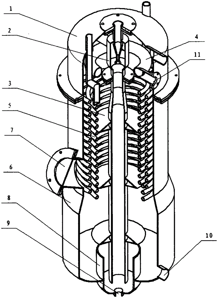
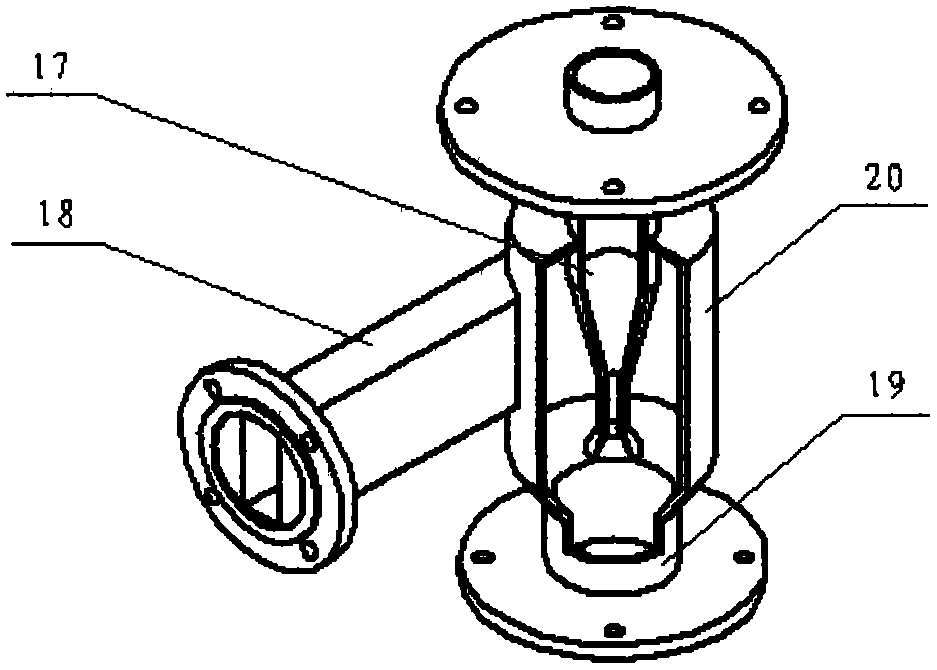
[0021] Embodiment 1: referring to accompanying drawing, a kind of composite condensing device of pyrolysis gas of biomass is characterized in that: it comprises: shell 6, top cover 1, gas-liquid mixer 2, guide pipe 3, cooling pipe 5, sprinkler 4;

[0022] The shell 6 has a cylindrical structure, with a primary condensate isolation area 8 at the bottom, a sewage outlet 9, and a liquid outlet 10 on one side. The condensed primary and secondary liquid products are stored in the primary condensate respectively. The liquid isolation area 8 and its peripheral space, the impurities therein are discharged from the sewage outlet 9 after precipitation; the liquid outlet 10 is connected with the oil pump 26, and the liquid mixture is delivered to the gas-liquid mixer 2 and the gas-liquid mixer 2 by the oil pump 26. The shower 4 is recycled;

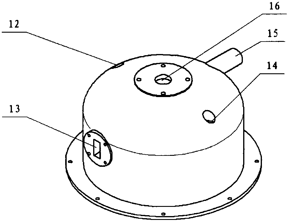
[0023] The top cover 1 is connected above the shell 6 by a flange, and together with the shell 6 wraps the remaining components inside; the nozzle...

Embodiment 2

[0028] Embodiment 2: In the composite condensing device of biomass pyrolysis gas described in Embodiment 1, a sight glass 7 is installed in the middle of the shell 6, which is convenient for observing the internal conditions and as a hand hole.


PUM


Abstract

The invention belongs to the technical field of energy chemical engineering, and particularly relates to a composite condensation device used in vehicle-mounted biomass thermal cracking equipment. The composite condensation device used in the vehicle-mounted biomass thermal cracking equipment comprises a housing (6), a top cover (1), a gas-liquid mixer (2), a cooling tube (5), a spraying device (4) and a guide tube (3). Two condensation procedures of ejection and spraying are adopted, secondary condensation can be performed on thermal cracking steam, the condensation time is shortened, secondary decomposition is avoided, and the liquid product yield is increased; a first-stage condensate partitioning area is arranged at the bottom of the housing, so that two stages of condensate can be respectively recycled; the second stage of the condensate is discharged out from a liquid outlet and is circulated by an oil pump so as to be used as a condensation medium; the internal components of the condensation equipment are compact in structure and reasonable in arrangement, the overall occupation area is effectively reduced, the condensation equipment is easy to disassemble and assemble, convenient to wash and repair, and particularly applicable to small-size thermal cracking systems or mobile operation equipment.

Description

technical field [0001] The invention belongs to the technical field of energy and chemical industry, and in particular relates to a condensing device. Background technique [0002] Rapid condensation is a crucial link in the biomass pyrolysis liquefaction process. It is generally required that the steam generated after pyrolysis be converted from gaseous state to liquid state and non-condensable gas in the shortest possible time, so as to avoid further decomposition of steam and improve the liquid state. Product yield and quality. [0003] In the field of biomass pyrolysis liquefaction, direct contact condensation has high heat exchange efficiency and relatively simple structure, and is one of the most widely used condensation methods at present. For direct contact condensation, the commonly used condensers are sieve plate towers and spray cooling towers. The sieve plate towers are larger in size, and the sieve plate and other components are easily blocked by tar and carbon...

Claims


Application Information

Patent Timeline
Patent Type & Authority Patents(China)
IPC IPC(8): B01D5/00C10B53/02C10B57/00
CPCY02E50/10
Inventor 司慧王霄常建民吴煜程琦孔金超
Owner BEIJING FORESTRY UNIVERSITY
Why Eureka
Try Eureka