
Laboratory continuous biogas anaerobic fermentation device

An anaerobic fermentation and laboratory-used technology, applied in the field of fermentation, can solve problems such as the difficulty in realizing the raw material temperature of the fermentation tank, insufficient biogas firepower, and backward production technology, so as to facilitate the production of biogas, improve fermentation efficiency and gas production rate, and ensure heating effect

Active Publication Date: 2015-02-18
XI'AN UNIVERSITY OF ARCHITECTURE AND TECHNOLOGY
View PDF4 Cites 12 Cited by
  • Summary
  • Abstract
  • Description
  • Claims
  • Application Information

AI Technical Summary

Problems solved by technology

Although my country's biogas project started as early as the 1960s, our production technology is still very backward. The main problems are: first, the gas production rate is low
The content of methane in biogas is only about 60%, and contains a small amount of hydrogen and hydrogen sulfide. In addition, non-combustible gases in biogas, including carbon dioxide, account for 20% to 45%, resulting in insufficient firepower of biogas
Second, gas production is unstable
For medium-temperature fermentation, the ideal temperature is about 35°C, and the temperature difference in the tank should not exceed 2°C. Usually, laboratory biogas fermentation devices use external water bath heating or built-in single element heating. Compared with external indirect heating, Built-in direct heating has small heat loss and low energy consumption; however, it is difficult to achieve uniform temperature of raw materials in the fermentation tank with single element heating

Method used


Image

  • Laboratory continuous biogas anaerobic fermentation device
  • Laboratory continuous biogas anaerobic fermentation device
  • Laboratory continuous biogas anaerobic fermentation device

Examples


Embodiment Construction

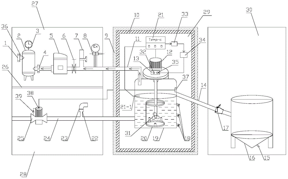
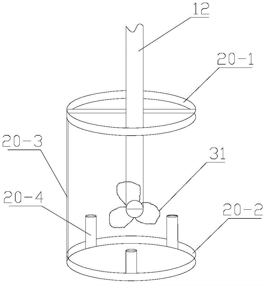
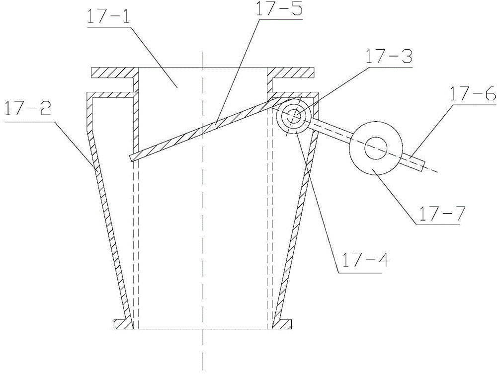
[0047] Such as figure 1 and figure 2 As shown, the present invention includes a first space, a second space and a third space arranged at intervals, and the middle part of the first space is provided with a gas collection and storage chamber 27 for separating the upper and lower parts of the first space to form an upper part and The dividing plate 26 of the lower feeding chamber 28, the second space is a fermentation chamber 29, the periphery of the second space is provided with an insulating layer, and the third space is a biogas residue biogas liquid chamber 30; the fermentation chamber 29 A fermenter 19, a fermentation temperature controller 21 and a vertical mixer 12 installed on the fermenter 19 are arranged inside, the stirring rod of the vertical mixer 12 is inserted into the inside of the fermenter 19, and the motor of the vertical mixer 12 Supported on the top of the fermenter 19 tank body, the bottom of the stirring rod of the vertical mixer 12 is equipped with a s...


PUM


Abstract

The invention discloses a laboratory continuous biogas anaerobic fermentation device. The laboratory continuous biogas anaerobic fermentation device comprises a gas collection and storage chamber, a feeding chamber, a fermentation chamber and a biogas residue and biogas slurry chamber, wherein a fermentation tank, a fermentation temperature controller and a vertical mixer are arranged in the fermentation chamber; a mixing blade and an electric heating element are mounted on the mixing rod of the vertical mixer; a plurality of outlets are formed in the sidewall of the body of the fermentation tank; a feeding pipe is arranged in the feeding chamber and a circulating pump and an exhaust pipe are connected to the feeding pipe; a gasholder is arranged in the gas collection and storage chamber, the middle lower part of the gas holder is communicated with the upper part of the fermentation tank by use of a gas collecting pipe, and a gas flowmeter, a pipeline valve, a gas compressor, a gas inlet valve and a gas distribution pipe are connected to the gas collecting pipe; a biogas residue and biogas slurry storage tank is arranged in the biogas residue and biogas slurry chamber, the middle upper part of the biogas residue and biogas slurry storage tank is communicated with the middle upper part of the fermentation tank by use of a waste discharge pipe and a flap valve, and a waste liquid outlet is formed in the bottom of the biogas residue and biogas slurry storage tank. The laboratory continuous biogas anaerobic fermentation device has the advantages that fermentation raw materials can be added to the fermentation tank any time and continuous biogas anaerobic fermentation can be realized based on the laboratory platform.

Description

technical field [0001] The invention belongs to the technical field of fermentation, and in particular relates to a continuous biogas anaerobic fermentation device used in a laboratory. Background technique [0002] In recent years, energy issues have become a restrictive issue for national development. Non-renewable energy sources such as coal, oil, and natural gas have affected the future development of the country due to over-exploitation. Therefore, it is imminent to seek and develop new renewable energy sources. As a renewable energy source, biogas fits well with the country's sustainable development strategy, and as an emerging fuel, it has been used on a large scale in some developed countries. Although my country's biogas project started as early as the 1960s, our production technology is still very backward. The main problems are: first, the gas production rate is low. The content of methane in biogas is only about 60%, and contains a small amount of hydrogen and ...

Claims


Application Information

Patent Timeline
Patent Type & Authority Applications(China)
IPC IPC(8): C12M1/38C12M1/36C12M1/34C12M1/107C12M1/02
CPCC12M21/04C12M23/34C12M27/02C12M41/12C12M41/34Y02E50/30
Inventor 云斯宁黄欣磊朱江杜婷婷胡谢利
Owner XI'AN UNIVERSITY OF ARCHITECTURE AND TECHNOLOGY
Learn More