Peak power intensifier and high peak power MOPA fiber laser

A fiber laser, peak power technology, applied in the direction of lasers, laser components, phonon exciters, etc., can solve the problems that the stability of the laser optical path system cannot be guaranteed, and the output power of the seed source is small, so as to suppress nonlinear effects and reduce The effect of optical fiber length and peak power enhancement

Inactive Publication Date: 2015-02-18
广东高聚激光有限公司 +2
View PDF7 Cites 8 Cited by
  • Summary
  • Abstract
  • Description
  • Claims
  • Application Information

AI Technical Summary

Problems solved by technology

[0006] The disadvantage of this method is that the output power of the seed source is small. Due to the multi-stage amplification to achieve the required power, and before each stage of amplification, an optical fiber isolator, a certain length of active optical fiber and the remaining optical fiber in each component are required. etc., it is easy to produce nonlinear effects inside the fiber, that is, the peak power of the above-mentioned entire fiber laser is suppressed at 25KW, which limits the further improvement of its output power, thereby inhibiting the enhancement of peak power
If the peak power is higher than 25KW, the stability of the laser optical system cannot be guaranteed

Method used


Image

  • Peak power intensifier and high peak power MOPA fiber laser
  • Peak power intensifier and high peak power MOPA fiber laser
  • Peak power intensifier and high peak power MOPA fiber laser

Examples


Embodiment 1

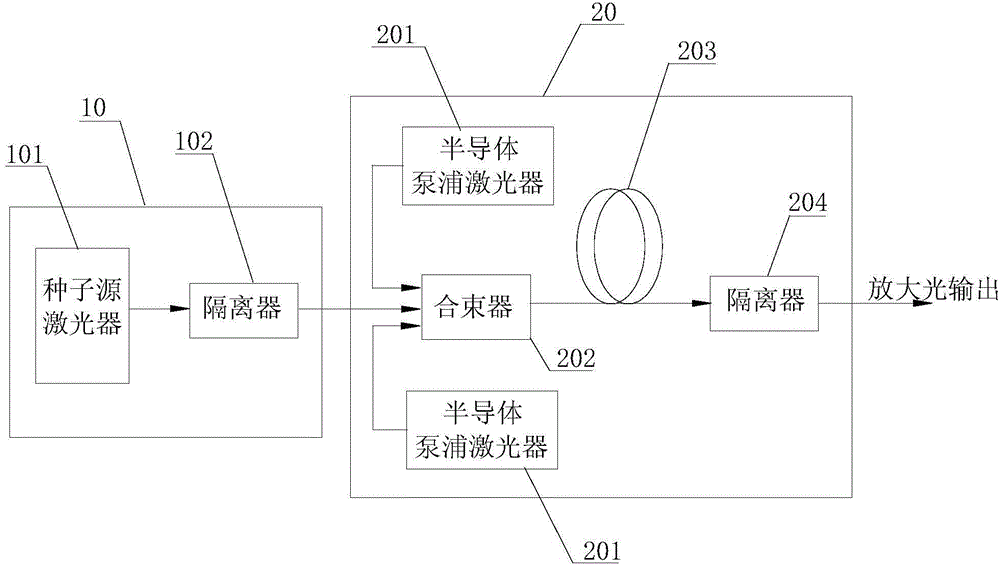
[0028] Such as Figure 5 The fiber laser shown includes a main oscillator component 1 and a power amplifier component 2 . Wherein, the main oscillator assembly 1 includes a seed source laser 11 and a forward isolator 12 , and the output end of the seed source laser 11 is connected to the input end of the forward isolator 12 by optical fiber fusion. The power amplification component 2 includes a plurality of semiconductor pump lasers 21 , a beam combiner 22 , and a peak power booster 23 . Wherein, the output ends of each semiconductor pump laser 21 and the forward isolator 12 are respectively coupled to the beam combiner 22 , and the output end of the beam combiner 22 is directly connected to the peak power booster 23 by optical fiber fusion. The structural composition of the peak power booster 23 is further introduced below:

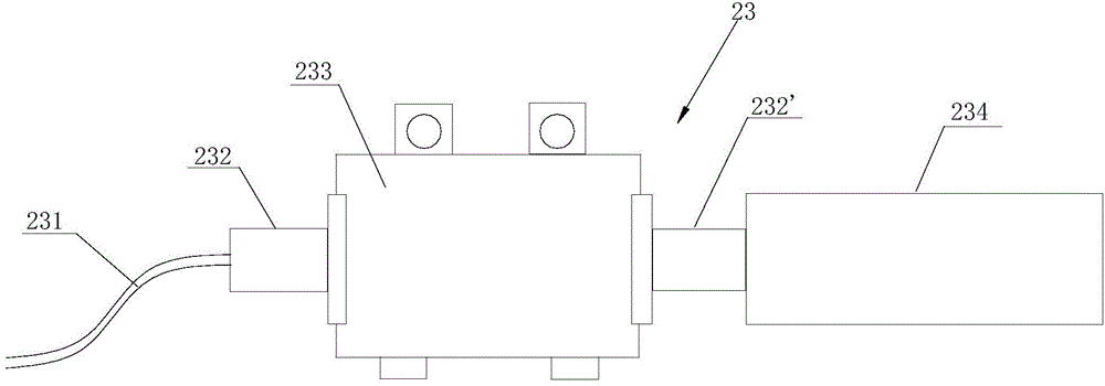
[0029] Such as image 3 The peak power booster 23 shown includes an input pigtail 231 with armor layer protection, a collimating lens, a semiconducto...

Embodiment 2

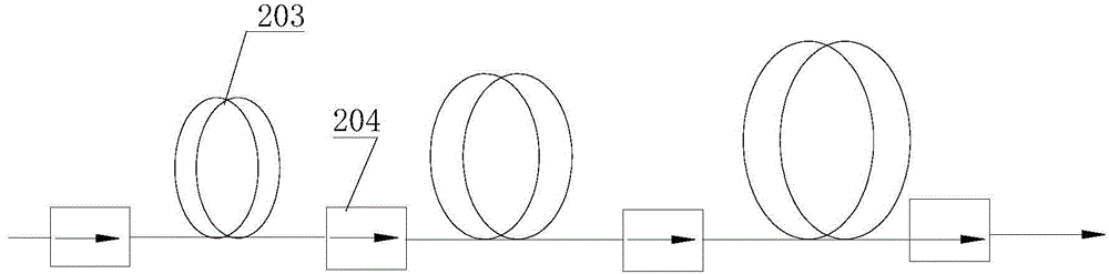
[0034] Such as Figure 6As shown, the difference between the fiber laser of this embodiment and the first embodiment is that a two-stage amplifying optical circuit 24 is also connected between the main oscillator component of the laser and the peak power booster, and the two-stage amplifying optical circuit is mainly composed of an active optical fiber and isolator. Taking the optical fiber MOPA laser in the background technology as an example, the first-stage amplification optical path is a seed pre-amplification optical path. If the output is 8ns, 100khz, 15mw, and the peak power is 18.75W, after passing through the second-stage amplification optical path, the output is 8ns, 100khz, 1W, peak power 1.25kw. The peak power intensifier of the present invention is directly fused at the output end of the second-stage amplifying optical path. Since the semiconductor pump module itself has an optical amplification effect, the magnification factor selected in this embodiment is 40 t...


PUM


Abstract

The invention relates to a peak power intensifier and a high peak power MOPA fiber laser. The peak power intensifier comprises a master oscillator assembly and a power amplification assembly. The master oscillator assembly comprises a seed resource laser and a forward isolator. The power amplification assembly comprises a plurality of diode-pumped lasers, a beam combiner and a peak power intensifier. The peak power intensifier comprises a diode-pumped module, a first collimating lens, a second collimating lens, an input tail fiber and an expanded beam lens. After a laser signal is output from the beam combiner, the laser signal sequentially passes through the first collimating lens, the diode-pumped module, the second collimating lens and the expanded beam lens, and then a high peak power laser signal is output. The peak power intensifier directly replaces a main amplification light path in an optical fiber MOPA structure, and the high-power isolator serves as the main amplification light path in the MOPA laser to directly output light, as a result, the light path optical fiber length can be reduced greatly, the nonlinear effect of a light path amplification system is effectively restrained, and the peak power output by the laser is increased.

Description

technical field [0001] The invention relates to a high-power MOPA fiber laser. Background technique [0002] Due to its compact structure, good light speed and quality, high efficiency, narrow line width, narrow pulse width and high peak power, fiber MOPA lasers can be widely used in marking, drilling, micromachining, military, laser medicine and other fields. [0003] The structure of the existing fiber laser is as follows figure 1 As shown, it usually includes a main oscillator part 10 and a power amplification part 20. The main function of the main oscillator is to generate high-quality seed light, and the output power can be large or small, so the output light is easier to achieve the required time domain, Frequency domain characteristics and maintain good beam quality; the main function of the power amplification part is to amplify the seed light, which is composed of one or several stages of fiber amplifiers, while ensuring the high beam quality of the output light an...

Claims


Application Information

Patent Timeline
Patent Type & Authority Applications(China)
IPC IPC(8): H01S3/10H01S3/067
Inventor 夏江帆何健豪刘汉斌赵青春
Owner 广东高聚激光有限公司
Why Eureka
Try Eureka