Engine oil returning structure

An engine and oil technology, applied in the installation/connection of lubricant purification devices, lubricating parts, lubrication indicating devices, etc., can solve the problem of unfavorable disassembly and maintenance of the arrangement position, inconvenient installation of oil filters, and unfavorable cleaning of expired oil, etc. problems, to avoid oil leakage to pollute the environment, reduce the risk of sticking, and achieve the effect of compact structure

Active Publication Date: 2015-03-25
ANHUI JIANGHUAI AUTOMOBILE GRP CORP LTD
View PDF6 Cites 8 Cited by
  • Summary
  • Abstract
  • Description
  • Claims
  • Application Information

AI Technical Summary

Problems solved by technology

[0010] like figure 2 As shown in the figure, in the downward arrangement, the oil filter is arranged toward the bottom of the chassis, that is, the height of the oil filter is located below the main oil passage, which has the advantage of being conducive to the emptying of the oil, but it is inconvenient to install the oil filter , and when the oil filter is disassembled, the oil will be directly discharged from the main oil passage of the engine, causing oil pollution to pollute the environment, and the arrangement position is not conducive to disassembly and maintenance
[0011] like image 3 As shown, in the upward arrangement, the oil filter is arranged towards the direction of the engine compartment cover, that is, the height of the oil collection filter is above the lowest end of the main oil passage. The advantage of this is that the oil filter is easy to install, but in When removing the oil filter, there will be oil in the main oil passage of the cylinder block, cylinder head and the oil filter. image 3 The engine oil below the dotted line cannot be discharged, resulting in the deposition of oil containing impurities, which is not conducive to the cleaning of expired engine oil and is not conducive to engine maintenance
Moreover, since there is oil containing impurities in the main oil passage, the oil deposited in the oil passage after maintenance will continue to contaminate the new oil.

Method used


Image

  • Engine oil returning structure
  • Engine oil returning structure
  • Engine oil returning structure

Examples


Embodiment Construction

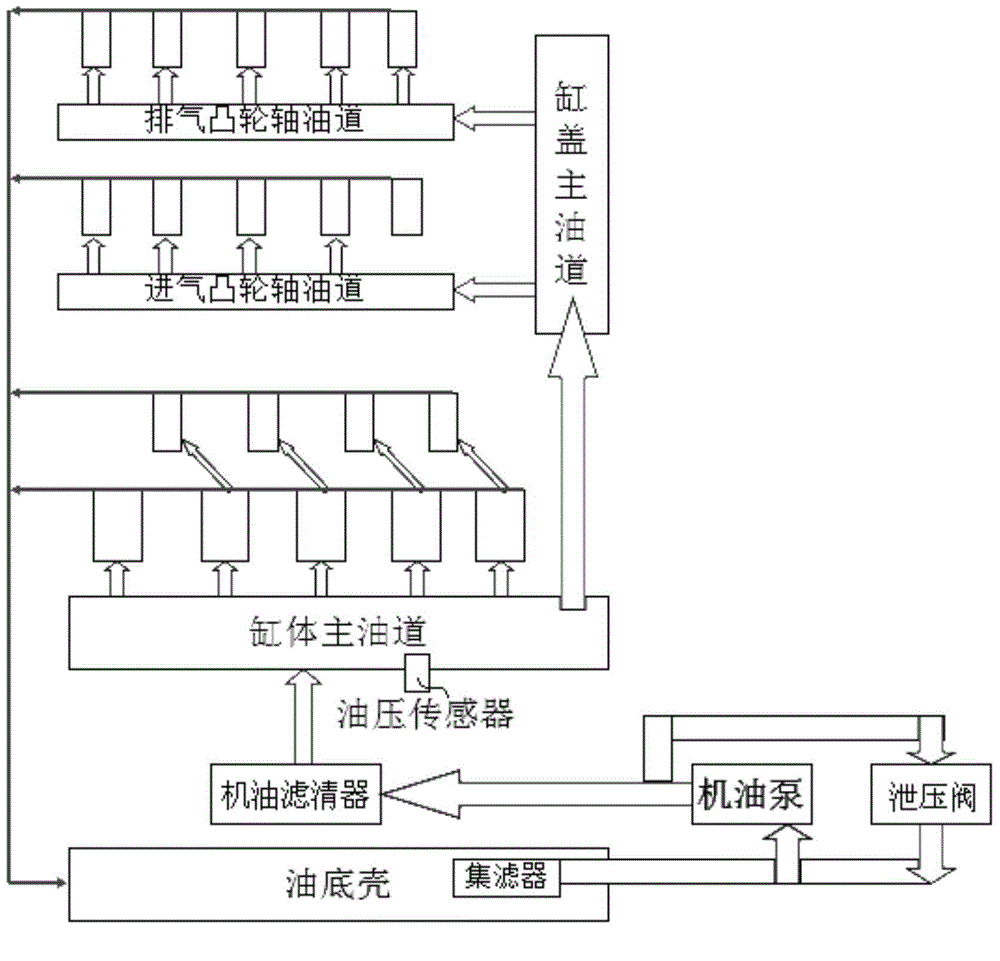
[0039] reference Figure 4 The engine oil return structure in the embodiment of the present invention also includes an oil pan, a filter, an oil pump, an oil filter, an oil pressure sensor, etc. In this embodiment, a solenoid valve is used as a pressure relief valve for practical use, and Figure 7 It can be seen that the solenoid valve is connected to an ECU (Electronic Control Unit, electronic control unit) and is controlled by the ECU. The oil in the oil pan passes through the filter, the oil pump and the oil filter in sequence, and then enters the main oil passage of the cylinder block, and then enters the branch oil such as the main oil passage of the cylinder head, the exhaust camshaft oil passage and the intake camshaft oil passage. Road, and finally return to the oil pan. The solenoid valve in this embodiment is connected to the oil filter and the oil pan. The oil pressure sensor measures the oil pressure of the oil entering the main oil passage of the cylinder in the oi...


PUM


Abstract

The invention provides an engine oil returning structure. The engine oil returning structure comprises an oil pan, a suction filter, an engine oil pump, an engine oil filter, an electromagnetic valve, an ECU and an oil pressure sensor. Engine oil in the oil pan sequentially passes through the suction filter, the engine oil pump and the engine oil filter to enter a cylinder main oil way, the electromagnetic valve is used for connecting the engine oil filter with the oil pan, the oil pressure sensor measures the pressure of the engine oil entering the cylinder main oil way from the engine oil filter and transmits oil pressure signals to the ECU, and the ECU controls the open degree of the electromagnetic valve according to the oil pressure signals to enable the engine oil filtered through the engine oil filter to flow back to the oil pan. By means of the engine oil returning structure, it can be guaranteed that the oil pressure can better meet the practical working requirements of an engine, and the engine oil returning structure is more environmentally friendly.

Description

Technical field [0001] The invention relates to the field of engines, in particular to an engine oil return structure. Background technique [0002] In the engine, the engine oil is continuously polluted by the wear particles of the engine and the impurities that fall into the outside world. At the same time, due to thermal oxidation, acid substances and insoluble colloidal deposits that are soluble in the engine oil are produced. Hard particles in these impurities will increase engine wear. Acids produce corrosive wear on the bearing bush. Glue can cause cementation between piston and piston ring, valve and valve guide. The price of the oil filter is to filter out the above-mentioned harmful impurities in the oil, protect the main engine parts and prolong its service life. [0003] In order to prevent the oil pressure of the lubrication system from being too high and increasing the power consumption of the engine, causing oil leakage at the sealing connection in the oil circuit,...

Claims


Application Information

Patent Timeline
Patent Type & Authority Applications(China)
IPC IPC(8): F01M11/03F01M11/10
CPCF01M11/03F01M11/10
Inventor 靳素华倪成鑫杨林强张应兵张建操刘彤苏晓芳董先瑜颜伟房程程王强李宁谢有路
Owner ANHUI JIANGHUAI AUTOMOBILE GRP CORP LTD
Why Eureka
Try Eureka