Flue gas desulfurization and denitrification method and device and application of flue gas desulfurization and denitrification device
A technology for desulfurization, denitrification, and flue gas, which is applied in the field of flue gas purification, can solve the problems of inability to realize desulfurization and denitrification reactions and process conditions, dioxins cannot be effectively removed, and heat cannot be effectively used, so as to reduce investment and operating costs, reduced power requirements, and the effect of reduced power requirements
- Summary
- Abstract
- Description
- Claims
- Application Information
AI Technical Summary
Problems solved by technology
Method used
Image

Examples
Embodiment 1
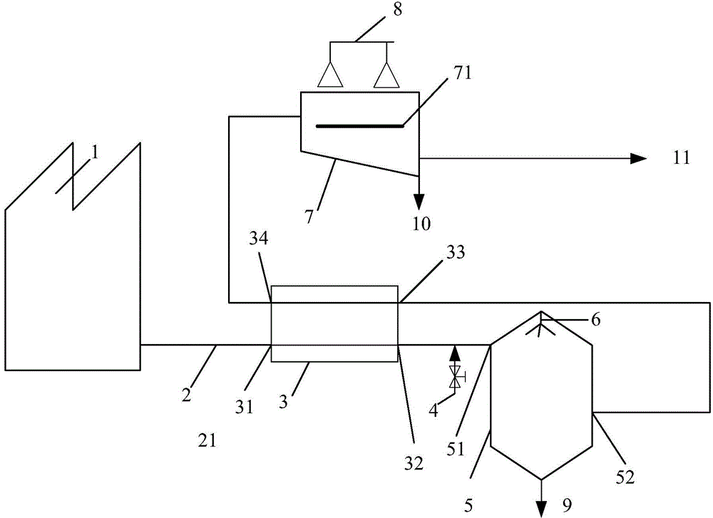
[0063] see figure 2 In the present invention, the flue gas is processed in two steps through the flue gas treatment tower and the irradiation reactor respectively. The temperature of the flue gas produced by boiler 1 is 130°C, and the SO in the flue gas x The content is 300ppm, and the NOx content is 200ppm.
[0064] figure 2 The components and connections of the electron beam flue gas desulfurization and denitrification device shown are as follows:
[0065] The boiler flue gas inlet 31 of the flue gas-flue gas heat exchanger 3 is connected to the boiler 1 through the first flue 21;
[0066] A flue gas treatment tower 5 on which a spray system 6 is installed; the boiler flue gas outlet 32 of the flue gas-flue gas heat exchanger 3 is connected to the flue gas inlet of the flue gas treatment tower 5 51 is connected with the second flue 22, and the ammonia injection control valve 4 is arranged on the second flue 22; the flue gas outlet 52 of the flue gas treatment tower 5...
Embodiment 2
[0074] see Figure 4 In the present invention, the flue gas is processed in two steps through the flue gas treatment tower and the irradiation reactor respectively. The flue gas temperature produced by boiler 1 is 150°C, the SOx content in the flue gas is 280ppm, and the NOx content is 200ppm.
[0075] Figure 4 The components and connections of the flue gas desulfurization and denitrification device shown are as follows:
[0076] The flue gas-flue gas heat exchanger 3, the boiler flue gas inlet 31 of the flue gas-flue gas heat exchanger 3 is connected to the boiler 1 through the first flue 21; the flue gas treatment tower 5, the flue gas treatment tower 5 is installed with a spray system 6; the boiler flue gas outlet 32 of the flue gas-flue gas heat exchanger 3 is connected with the flue gas inlet 51 of the flue gas treatment tower 5 through the second flue 22, and the first The second flue 22 is provided with an ammonia injection control valve 4; the flue gas outlet 52 ...
Embodiment 3
[0082] see Figure 5 In the present invention, the flue gas is processed in two steps through the flue gas treatment tower and the irradiation reactor respectively. The flue gas temperature produced by boiler 1 is 150°C, the SOx content in the flue gas is 280ppm, and the NOx content is 200ppm.
[0083] Figure 5 The components and connections of the shown flue gas desulfurization and denitrification device are similar to those in Example 2, specifically as follows:
[0084] The flue gas-flue gas heat exchanger 3, the boiler flue gas inlet 31 of the flue gas-flue gas heat exchanger 3 is connected to the boiler 1 through the first flue 21; the flue gas treatment tower 5, the flue gas treatment tower 5 is installed with a spray system 6; the boiler flue gas outlet 32 of the flue gas-flue gas heat exchanger 3 is connected with the flue gas inlet 51 of the flue gas treatment tower 5 through the second flue 22, and the first The second flue 22 is provided with an ammonia inject...
PUM
| Property | Measurement | Unit |
|---|---|---|
| Wavelength | aaaaa | aaaaa |
Abstract
Description
Claims
Application Information
 - Generate Ideas
- Intellectual Property
- Life Sciences
- Materials
- Tech Scout
- Unparalleled Data Quality
- Higher Quality Content
- 60% Fewer Hallucinations
Browse by: Latest US Patents, China's latest patents, Technical Efficacy Thesaurus, Application Domain, Technology Topic, Popular Technical Reports.
© 2025 PatSnap. All rights reserved.Legal|Privacy policy|Modern Slavery Act Transparency Statement|Sitemap|About US| Contact US: help@patsnap.com