Fuel drying device used for direct combustion biomass power station

A drying device and biomass technology, applied in drying, dryer, progressive dryer and other directions, can solve the problems of increased power consumption, increased water vapor content, frequent failures, etc. Easy to block, high throughput effect

Inactive Publication Date: 2015-04-01
闵公发
View PDF10 Cites 21 Cited by
  • Summary
  • Abstract
  • Description
  • Claims
  • Application Information

AI Technical Summary

Problems solved by technology

The moisture content of the fuel exceeds the standard, and it cannot be dried, which causes the ignition point of the fuel in the furnace to move backward. The heat is not completely absorbed by the boiler, and it is discharged with the flue gas, so the temperature of the flue gas rises, and because the excess moisture enters the furnace for heating Expansion, in addition to absorbing a large amount of energy, will also consume more fuel; and the water vapor content in the flue ga

Method used


Image

  • Fuel drying device used for direct combustion biomass power station

Examples


Embodiment Construction

[0018] The present invention will be further described below in conjunction with the accompanying drawings and specific embodiments, so that those skilled in the art can better understand the present invention and implement it, but the examples given are not intended to limit the present invention.

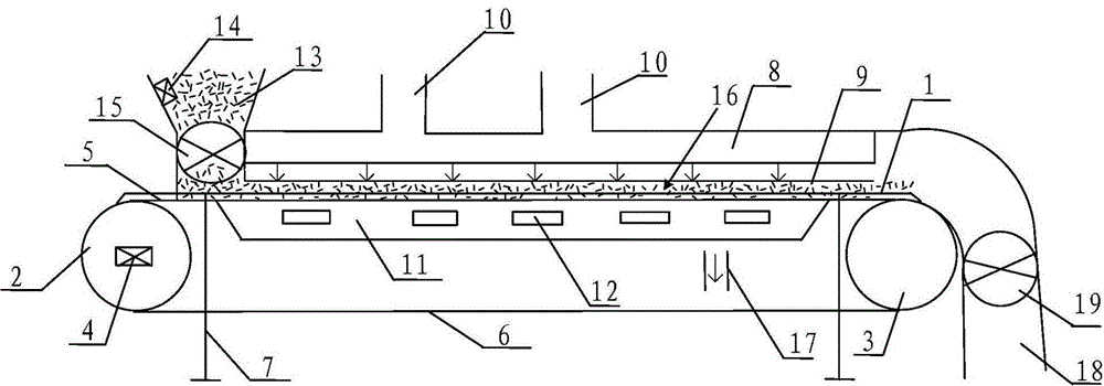
[0019] The invention provides a fuel drying device for a direct-fired biomass power plant, such as figure 1 As shown, it includes a conveyor, and the conveyor includes a frame 1, and the frame 1 is equipped with a ventilated mesh steel mesh conveyor belt driven by upper and lower layers, including an upper conveyor belt 5 and a lower conveyor belt 6. Both ends of the frame 1 have a main driving wheel 2 and a driven wheel 3. The main driving wheel 1 is connected to a motor to provide power for the conveyor belt drive of the conveyor. The motor is equipped with a frequency converter 4 to control the speed of the conveyor. Conveyor belt drive speed. One end of the frame where the ma...


PUM


Abstract

The invention discloses a fuel drying device used for a direct combustion biomass power station. The fuel drying device comprises a conveyor; the conveyor is provided with an upper conveying belt for conveying of an upper layer and a lower conveying belt for conveying of a lower layer; a hot air box is installed above the upper conveying belt; the bottom of the hot air box is installed with a hot air uniform plate; a plurality of hot air inlets are formed in the top of the hot air box; a cold air box is arranged between the upper conveying belt and the lower conveying belt of the conveyor; a feeding hopper is arranged above a head of the conveyor; the rear part of the conveyor is installed with a discharge hopper; and a material layer room is arranged between the hot air uniform plate and the upper conveying belt. The fuel drying device can recycle flue gas waste heat of the power plant to achieve the fuel drying of the direct combustion biomass power station, is energy-saving and environment-friendly; and at the same time, a large amount of fuel can be process, so that the demand for fuel of the power station can be met. The drying device is good in liquidity and has no requirements on the shape of the fuel, and congestion in the drying process is avoided.

Description

technical field [0001] The invention relates to a fuel drying device used in a direct-fired biomass power plant. Background technique [0002] At present, there is no equipment directly used for fuel drying of direct-fired biomass power plants in China, and the equipment related to biomass drying is only rotary kiln and tunnel type radiation furnace. Similar to the equipment for drying bulk biomass fuels is the rotary kiln, which can solve the drying of sawdust biomass. The traditional rotary kiln is composed of a large cylinder with a thicker diameter and a relatively long length, namely the material cylinder. The cylinder is supplemented by an electric motor to drive the gear. When rotating, the material runs from the upper end to the lower end under the action of gravity and inclination. The hot air enters from the upper end of the barrel and runs in the same direction as the material. The lower end of the barrel is equipped with a material outlet and an air material s...

Claims


Application Information

Patent Timeline
IPC IPC(8): F26B15/18F26B21/00
Inventor 闵公发邵菊花
Owner 闵公发
Why Eureka
Try Eureka