A Nanoscale Amplitude Measurement Method of Medium and High Frequency Vibration Under Low Frequency Random Disturbance
A random disturbance, high-frequency vibration technology, applied in measuring devices, measuring ultrasonic/sonic/infrasonic waves, instruments, etc., can solve the problem of poor measurement accuracy of weak vibration amplitude, and achieve the effect of improving measurement accuracy
- Summary
- Abstract
- Description
- Claims
- Application Information
AI Technical Summary
Problems solved by technology
Method used
Image
Examples
specific Embodiment approach 1
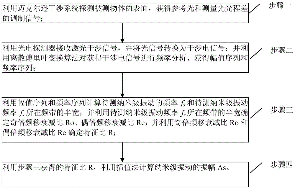
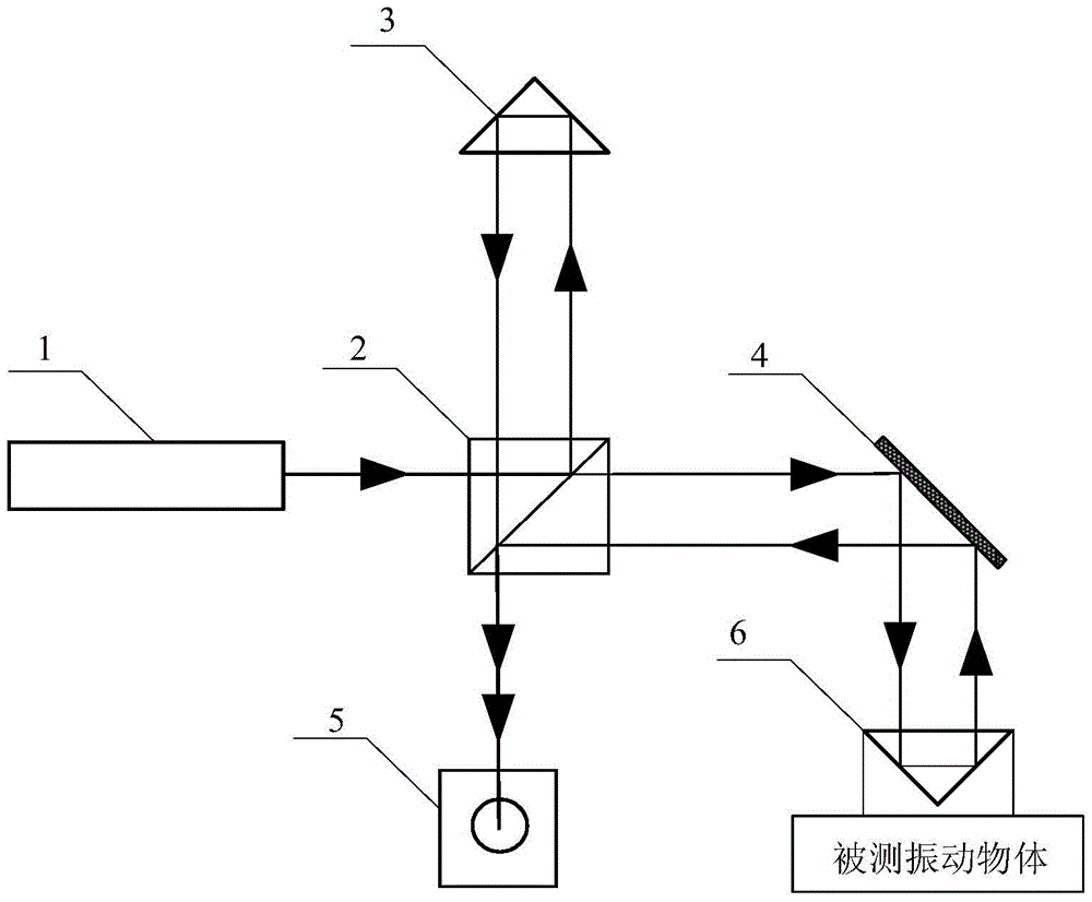
[0018] Specific implementation mode 1. Combination figure 1 and figure 2 Describe this embodiment, the method for measuring the nanoscale amplitude of medium and high frequency vibration under low-frequency random disturbance described in this embodiment, the method is realized based on the Michelson detection system, the system includes a laser 1, a beam splitter 2, and a corner cone prism 3 , mirror 4, photoelectric receiver 5 and No. 2 corner cube prism 6;
[0019] The laser light emitted by the laser 1 is separated by the beam splitter 2 and the beams are respectively incident on the No. 1 corner cube 3 and the reflector 4. The beam returned by the No. 1 corner cube 3 is incident on the beam splitter 2, and the beam after passing through the beam splitter is incident on the On the photosensitive surface of the photoelectric receiver 5, the light beam reflected by the reflector 4 is incident on the No. 2. The light beam after 2 is incident on the photosensitive surface o...
specific Embodiment approach 2
[0025] Specific embodiment 2. This embodiment is a further description of the nanoscale amplitude measurement method of medium and high frequency vibration under low-frequency random disturbance described in specific embodiment 1. The optical path difference between the reference light and the measurement light described in step 1 The modulation signal of is obtained by:
[0026] According to the basic principle of Michelson interference, the amplitude distribution of reference light:
[0027] E. b (t)=A b sin(ω 0 t+kz b +φ) (1)
[0028] In the formula, ω 0 is the reference optical angular frequency,
[0029] k is the wave number, λ is the laser wavelength;
[0030] Ф is the initial phase of the laser beam;
[0031] where A b is the reference light amplitude, t is the time, z b is the reference light arm length, c is the speed of light in vacuum, f 0 For the frequency of the laser beam, measure the amplitude distribution of the light:
[0032] E. c (t)=A c ...
specific Embodiment approach 3
[0045] Specific Embodiment 3. This embodiment is a further description of the method for measuring the nanoscale amplitude of medium and high frequency vibration under low-frequency random disturbance described in Embodiment 1. In step 2, the photodetector is used to receive the laser interference signal, and the The expression of the interference electrical signal in converting the optical signal to the interference electrical signal is:
[0046] The interference electrical signal is obtained by converting the light intensity signal, and the expression of the light intensity signal received by the photodetector is:
[0047]
[0048] Using Bessel's identity Expand the above light intensity signal as f s and f e The interferometric electrical signal is obtained as the sum of harmonic terms of the fundamental frequency:
[0049]
[0050] where x 1 =2kAe,x 2 =2kAs, j is an imaginary number symbol, β is a constant, is the phase angle, J n is the nth order Bessel fun...
PUM
 Abstract
Description
Claims
Application Information
 - R&D
- Intellectual Property
- Life Sciences
- Materials
- Tech Scout
- Unparalleled Data Quality
- Higher Quality Content
- 60% Fewer Hallucinations
Browse by: Latest US Patents, China's latest patents, Technical Efficacy Thesaurus, Application Domain, Technology Topic, Popular Technical Reports.
© 2025 PatSnap. All rights reserved.Legal|Privacy policy|Modern Slavery Act Transparency Statement|Sitemap|About US| Contact US: help@patsnap.com


