
Gamma-ray time detection device and manufacturing method of detector thereof

A detection device and detector technology, applied in the field of radiation detection, can solve the problems of supporting time detectors and photomultiplier tubes with few varieties and large volumes, and achieve the effects of reducing the volume, increasing the surface area, and expanding the scope of application

Inactive Publication Date: 2015-04-08
中国人民解放军第二炮兵装备研究院第六研究所
View PDF2 Cites 12 Cited by
  • Summary
  • Abstract
  • Description
  • Claims
  • Application Information

AI Technical Summary

Problems solved by technology

BaF 2 The fast luminescent component of the crystal is in the ultraviolet band, which does not match with many photoelectric conversion devices (such as photodiodes, avalanche diodes, silicon photomultiplier tubes, and borosilicate glass photomultiplier tubes), so they cannot be used with these devices to form time detectors, such as The sensitive waveband of borosilicate glass photomultiplier tube Hamamatsu R9800 is from 300nm to 650nm, and its peak is at 420nm. For BaF 2 The luminescent fast component of the crystal hardly responds, so BaF cannot be used 2 Crystal and Hamamatsu R9800 photomultiplier tube form a high-performance time detector
There are very few types of photomultiplier tubes for quartz windows, the price is expensive, and the volume is much larger than that of photodiodes, avalanche diodes, and silicon photomultiplier tubes. These are problems that affect their widespread use.

Method used


Image

  • Gamma-ray time detection device and manufacturing method of detector thereof
  • Gamma-ray time detection device and manufacturing method of detector thereof
  • Gamma-ray time detection device and manufacturing method of detector thereof

Examples


Embodiment Construction

[0043] In order to make the object, technical solution and advantages of the present invention clearer, the present invention will be described in further detail below in conjunction with specific embodiments and with reference to the accompanying drawings.

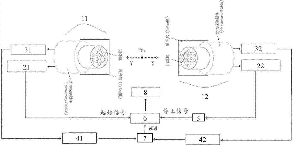
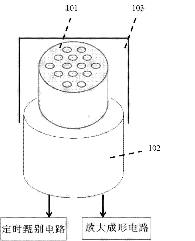
[0044] According to one aspect of the present invention, a kind of γ-ray time detection device is proposed, figure 1 is a schematic structural view of a gamma-ray time detection device according to an embodiment of the present invention, as figure 1 As shown, the time detection device includes: a first detector 11, a second detector 12, a first timing discrimination circuit 21, a second timing discrimination circuit 22, a first amplification and shaping circuit 31, a second amplification and shaping circuit 32, The first single-track pulse analyzer 41, the second single-track pulse analyzer 42, the delay circuit 5, the time-amplitude conversion circuit (TAC) 6, the coincidence circuit 7 and the multi-channel analyzer 8,...


PUM


Abstract

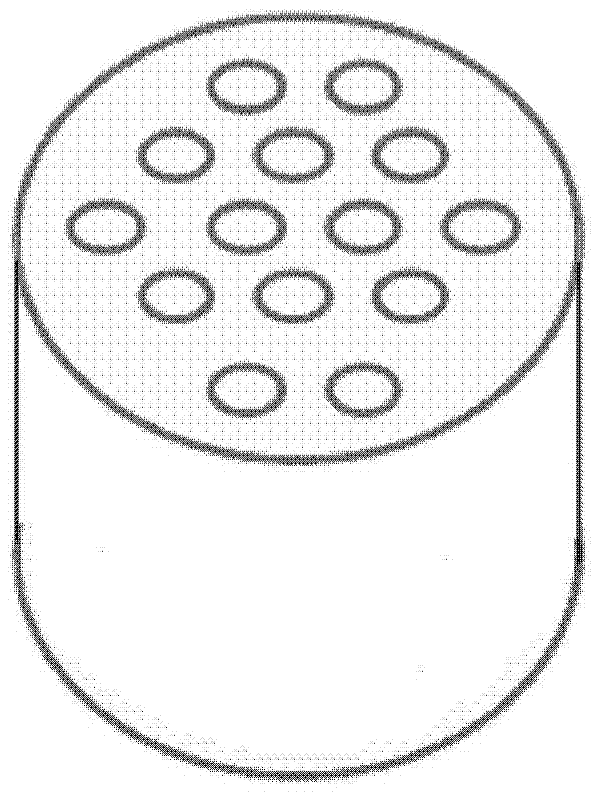
The invention discloses a gamma-ray time detection device and a manufacturing method of a detector thereof. The device comprises the detector, a timing discriminator circuit, an amplifying forming circuit, a single channel pulse analyzer, a delay circuit, a time-amplitude conversion circuit, a coincident circuit and a multichannel analyzer. According to the gamma-ray time detection device and the manufacturing method of the detector thereof, a BaF2 crystal, POPOP and silicone rubber are adopted as materials for manufacturing a composite scintillation through adopting a special process, and processing to a honeycomb briquette shape to form the detector, so that fluorescent light with wave length being 220nm emitted by the BaF2 crystal can be converted to visible light with wave length being around 420nm, and a photoelectric multiplier of a quartz window is not needed anymore, so that the application range is greatly expanded; with the structural design of the honeycomb briquette shape, the surface area of the scintillation is increased, so that after part of flare light is refracted, the refracted flare light can be transmitted through air medium to reach a photoelectric detector, the time for reaching the photoelectric detector is shortened, the signal initial stage can be risen quickly, and a timing discriminator can be conductive to timing, so that the timing precision of the gamma-ray time detection device is improved.

Description

technical field [0001] The invention belongs to the technical field of radiation detection, and in particular relates to a gamma ray time detection device and a method for manufacturing the detector. Background technique [0002] The time measurement of γ-rays is an important aspect of radiation detection technology, which can be used in many fields such as positron annihilation lifetime measurement and positron tomography. [0003] The usual time measurement method is to use a time detector composed of a plastic scintillator coupled with a photomultiplier tube to measure time. The luminescence decay time of the fast-response plastic scintillator is on the order of 1ns, which has excellent time resolution performance and can also match a variety of silicon A variety of photoelectric conversion devices such as boron glass photomultiplier tubes, photodiodes, and avalanche diodes form a time detector. However, due to the low atomic number of the time detector, the stopping pow...

Claims


Application Information

Patent Timeline
IPC IPC(8): G01T1/20G01T1/202
Inventor 刘军辉程金星赵锋涛温伟伟吴友朋胡玉新周文平王春安
Owner 中国人民解放军第二炮兵装备研究院第六研究所
Learn More